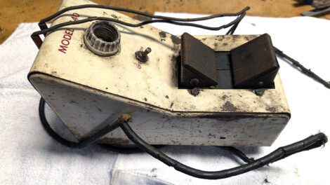
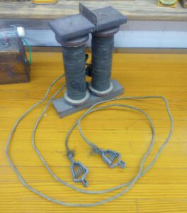
I recently received an email requesting help in converting a growler to a magnet charger. I’m sure our younger readers are asking, “How can a gallon of carry-out draft beer be converted to a magnet charger?” That’s a different kind of growler. Growlers, like Figure 1, were found in all automotive and electric motor repair shops until the 1960s or 70s. By laying a starter or generator armature on the growler, a segment that was shorted or open could be identified and repaired. With today’s no-repair-just-replace-it culture, growlers are no longer used. They can be found at swap meets, garage sales, and the like for a few bucks, and can then, with very little modification, be turned into a very nice magnet charger.
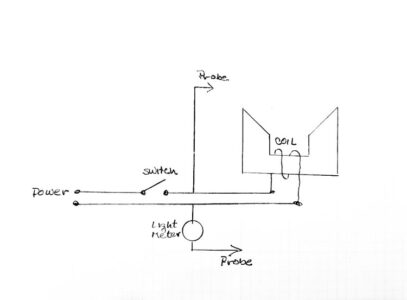
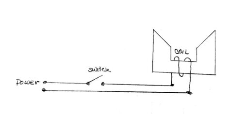
Growlers are very simple machines: an electro-magnet, a means of measuring current (amp meter or the brightness of a light bulb), and two probes. This growler is a light bulb version; others will have an amp meter in place of the socket. Figure 2 is the growler schematic.
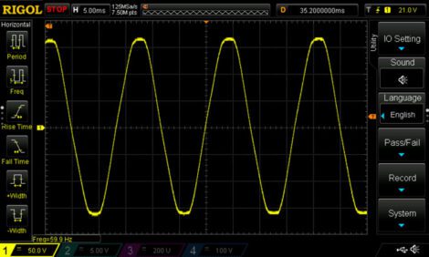
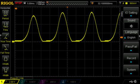
The growler is driven from the 120V, 60Hz AC line shown in Figure 3. The midpoint, top to bottom, marked with the yellow small 1 on the lower left, is 0V. The line voltage increases from 0V to +170V, then decreases toward 0V, going negative to -170V before returning to 0V and starting over again. That whole process takes 1/60 of a second. Because only a brief moment of time is spent at +170V and -170V, the amount of work that can be done is only the 120V, which is what your meter will read.
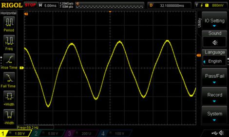
When the growler switch is closed and that AC voltage is applied to the coil of the electromagnet, an AC current begins to flow in the coil (Figure 4). That alternating current is a bit like a one-lane road construction site. Cars travel in one direction for a short interval of time, then travel in the opposite for another short period of time. Looking at Figure 2, this AC current flips the growler’s black 45 degree-angled pole pieces between N and S poles every 1/120 of a second. This rapid oscillation of the poles creates a small vibration and hum, or growl (hence, they became known as “growlers”). If a magnet were placed on the growler’s black pole pieces (Figure 1), it would quickly be totally demagnetized, as the tiny magnetic domains in the iron became disorganized as they tried to realign 60 times every second. Clearly, not the desired outcome.
To recharge a magnet, a very strong one-direction external magnetic field must be passed through the magnet with the proper polarity or direction. This strong field puts a torque on the magnetic domains that have become misaligned over time and realigns them so they again add to the overall magnet’s strength. The basics of magnet charging are clearly defined in the article “How to Build a Magnet Charger for $40.”
To convert the growler to a magnet charger, two things must be done. First, the growler coil needs to be fed with a DC or single direction current and, second, the growler pole pieces must be mechanically planarized so that a magnet being charged gets good contact. There are two simple ways to feed the coil DC current; planarizing the pole pieces is a more difficult task.
Begin the conversion with a good cleaning and removal of the two probes and connection to the meter or light bulb socket. The probes and meter won’t be used in the magnet charger configuration. It’s very likely that the old power cord will also need to be replaced. What’s left is a power cord, switch, and a big, heavy electromagnet (Figure 5).
Coils (or inductors, as engineers call them) have some interesting attributes, often discussed in Gas Engine Magazine and Farm Collector. Their ability to store energy allows both high- and low-tension ignitions to create a spark. Another useful attribute is that the impedance to current in inductors is frequency-dependent. The growler coil in Figure 1 passes 7.5A at 120V 60Hz and, by Ohm’s Law, looks like 16Ω; but that same 120V now at 30HZ will pass 15A and, therefore, look like 8Ω. At DC, the inductor in Figure 1 is only 1.4Ω.
This frequency dependence becomes important when making the simplest conversion from growler to charger. This simplest conversion will be called the 12V charger.
Separate the two wires at the end of the power cord. Label one wire with a (+) and terminate each wire with a battery clamp. With one wire labeled (+), the growler always come up with the same pole piece N and S polarity. The growler coil will likely have a DC resistance between 1.25 and 2.0 Ohms and can be directly connected to a solid 12V battery. If the coil maintained the 16Ω oresistance it has at 60Hz, there would be only 0.75A of current and make for a very poor charger. But, at DC, the coil in Figure 1 is only 1.4Ω, and a 12V battery will drive a very nice 8.5A. This 12V conversion produces a pretty good charger, every bit as good as a small 1920s charger, similar to Figure 6.
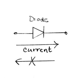
The 12V charger is pretty good but the email requested the best possible charger. By adding a two-terminal solid-state diode in series with one wire of the 120V AC line, a half wave rectified, one direction, current is produced. The solid-state diode is the simplest device in the transistor family. It has two terminals and allows current to pass through it unimpeded in one direction while allowing no current to flow through it in the opposite direction (Figure 7).
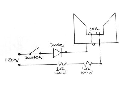
With the diode added, current through the coil is in one direction only, so each pole piece of the charger will remain one polarity, Figure 9. When Figure 9 is compared to Figure 4, the negative half cycle of current is removed. The frequency dependence of inductors shows up here also. With the half-wave rectified line, the current at 120V is higher than the original growler current and, therefore, 2 Ohms of high-power resistance is added. The final schematic of an excellent 120V magnet charger is shown in Figure 8.
Each resistor is 1 Ohm 100 watt. A pack of five was found on Amazon for $10. The diode is rated at 1000V and 20A. A pack of 20 diodes was found on Amazon for $7.50.
Some readers of this article that believe taping or banging on the magnet while it’s being recharged will improve the process. There seems to be no proof of that, but the reverse is demonstrable. Mechanical stress is a known method to degrade magnets. Further, many things in the physical world follow the rule of reciprocity, meaning they’re reversible. Whether banging on the magnet during recharge is proven or unproven, the 120V charger slams a very strong magnetic field on the magnet 60 times per second. This intense intermittent magnetic field will produce a mechanical shock that may improve the magnet recharging.
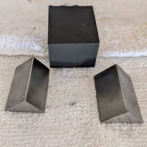
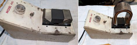
The final and most difficult task is planarizing the growler pole pieces. In general, each original growler pole piece will be at a 45 degree angle, but needs to be made horizontal and level. There are likely several ways to accomplish that. For this design, two 45 degree steel pieces and a non-magnetic spacer were cut, Figure 10. The external view of the finished charger with the planarized pole pieces is shown in Figure 12. The largest horseshoe magnet in the author’s inventory is ready to be recharged in Figure 14. Larger steel bar stock could be tack welded to the 45 degree pieces and charging blocks can be added for a universal charger.
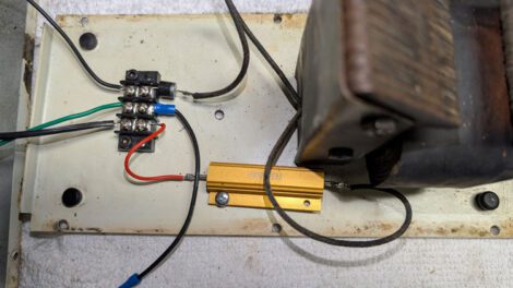
Figure 11 is an internal view of the final 120V charger. A terminal block was added, only because in writing this paper several experiments were run that required disassembly. The terminal block isn’t necessary; the components can be directly soldered together and covered with tape or shrink tubing. A single 2 Ohm resistor was used in this build, but it’s highly recommended that two 1 Ohm resistors in series be used. The diode is the small cylindrical-shaped device attached to the terminal block with the silver banded end facing the coil. If the diode is reversed, all is well; the negative current will flow, and the positive current will be blocked, reversing the growler’s magnetic poles.
So, how well do the 12V and 120V magnet chargers function? The magnetic field strength of the 12V charger was measured and compared to several chargers similar to that of Figure 6. The measured strength was a bit higher than any of that style the author has measured, new or antique, making it a nice charger.
To measure the 120V charger, the spark energy of a John Deere magneto was initially measured using a magnet not previously recharged. When the magnet was left on the 120V charger for 90 seconds, the magneto’s spark energy improved a whopping 400%. The magnet was then put on the big industrial Weidenhoff 818 charger (Figure 13) described in “The Weidenhoff 818 Charger.” After 90 seconds the Weidenhoff was able to improve the spark energy only another 20%. The conversion of an automotive growler to the 120V magnet charger results in a charger much better than the author expected.
The 120V charger produces more than 800 watts of magnetic energy to pass through the magnet being charged while the 12V charger produces less than 100 watts of magnetic energy. If a growler is to be converted, even though it requires a diode and a pair of resistors, the 120V model is highly recommended. Some readers may wonder why not use a full wave bridge rather than a single diode. With the bridge, the coil begins to look like 1 or 2Ω, resulting in excessive power that must be dealt with.


