After the Evac1 article was originally published in the February/March 2020 issue of Gas Engine Magazine, I received several emails asking for help on other types of buzz coils already built but for some reason didn’t work. My first advice was to throw what they had away and build an Evac1, which is simpler, smaller, cheaper, hotter, and has better long-term reliability. Do I sound a bit biased there?
Most of the non-functioning circuits that the emails were asking about were built around the automotive relay and a standard 1970s type 12V car coil. The common complaint was that it buzzes but has a very puny or nonexistent spark. Realizing there must be a lot of dead ones laying around out there and that we are all different with some of us preferring an old-fashioned buzz coil over the electronic Evac1, I decided to take a look.
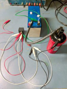
Over the years, I have built several circuits with embedded relays, but I had never built a relay-driven buzz coil. Five minutes in the shop and I had one up and running, at least buzzing (Figure 1). But, like the emails, I had a very puny spark. After playing around a bit, I found that some coils work fine with some relays and not with others. It seems to be luck if your relay and coil work together. If there is any trend, it seems the high-performance coils are the least likely to work with all relays.

Figure 2 is the basic schematic that I used as well as the configuration I received the most emails on. It will show up several times in a Google search so it’s difficult to give credit to the originator. It is identical to the generic Model T buzz coil where the mechanical flapper of the Model T is replaced by the relay and the internal coils are replaced by the automotive coil. The capacitor you see here is buried inside the Model T buzz coil box. There are other versions of the relay buzz coil that vary slightly from Figure 2. For example, the bottom lead of the capacitor can go to pin 30 as shown or to pin 85 or to the negative (-) terminal of the coil or even the negative terminal of the battery. Also, the engine timing switch can be in the relay pin 85, the coil negative lead to ground. Use whichever connection is most convenient.
First, a word on how it is supposed to function. At the local automotive store, the relay will likely be called a 5-pin or 5-lug relay, meaning it has five contacts on the bottom. An engineer would call it a single-pole, double-throw relay (SPDT). Figure 3A is the schematic of a 5-pin relay unpowered.

Internally, a relay has a pivoting arm (called the movable) on a hinge, an electromagnet, and a spring. Without power, the spring holds the movable pin 30 against the normally closed (NC) contact pin 87A, as shown in Figure 3A. In this unpowered condition, there is a short circuit or closed switch from pin 30 to pin 87A. When power is applied to the electromagnet (Figure 3B), the magnetic pull is much stronger than the spring, and the pivot arm is pulled away from the 87A contact and placed firmly against the normally open (NO) pin 87 contact. In the powered condition, the pin 30 to pin 87A path is now an open switch but the pin 30 to pin 87 path becomes a closed switch. Both the pin numbers and pin configuration have been standardized across the industry. Figure 4A is the bottom view; in most cases the pins will be numbered on the bottom as seen here. Sometimes a schematic will be stamped on the side or top, Figure 4B.

Figure 5 is an internal view of the relay. As can be seen, the electromagnet consumes most of the internal space. In this particular relay, the spring is an L-shaped affair around the movable hinge. I have seen others that were compression springs as well as the usual tension type. As a side note, generic Model T buzz coils also have an electromagnet to drive the flapper. It is often under the flapper, in the box, buried in the black tar. It’s probably unnecessary to expand here, but the normal function of a relay is to use a small amount of power to control a lot of power. For example, the electromagnet might be driven by your engine computer and require less than 100mA (0.1 Ampere) to energize. The pin 30 and 87 might connect the battery to the cooling fan at 30A, thus using 0.1A to control 30A.

To understand the operation, we need to understand some electromagnet characteristics. First, they do not respond to voltage. They respond to current; the more current the stronger the magnet. In the case of the relay I was using, it takes 80mA of current for the electromagnet to overpower the spring and pull the movable off of terminal 87A onto terminal 87. Also, from experience, we know that the closer we get metal to a magnet, the stronger the magnet seems to be. The same here, once the electromagnet has pulled the movable over against itself, it no longer needs as much current to hold it there. Once energized, the coil current can be reduced, 55mA in my case, before the spring overpowers the electromagnet and pulls the movable back to pin 87A. The final characteristic that is important is that current in a coil can’t change instantly. When voltage is applied to a coil, the electromagnet here, the current does not jump to some high value, rather it starts at zero and slowly ramps up to some final value. In a similar manner, when voltage is removed from a coil, the current does not immediately cease, rather it slowly ramps down. For a better understanding of coils, current and dwell see “An Interesting Ignition Problem” or “The Low-Tension Ignition System.”
Figure 6 is the essential parts of the vibrating portion of the buzz coil. Let’s watch what happens. The moment the switch, at the bottom (representing the engine timer switch), is closed, we are in the “on” state, and 12V appears on pins 87A and 86. But from the above discussion, we know nothing observable happens because initially the electromagnet coil current into pin 86 is zero. Now, however, the current into pin 86 and out of pin 85 to ground begins to increase above zero. In my relay, after about 3.5mS, the current reaches 80mA, and the electromagnet pulls the movable over against itself, disconnecting pins 87A and 86 from the 12V. Again, nothing much happens on the outside, the 80mA is well above the 55mA needed to hold the movable in the “off” state, and we know the coil current can not go to zero immediately. By pulling current out of the capacitor, the electromagnet coil current continues to flow but begins its ramp down. After 1mS, in my case, the coil current drops down to 55mA and the electromagnet releases the movable. At that point, 12V is again attached to 87A and 86 and the process begins all over again. The relay chatters back and forth between those two positions. The various relays I tried all chattered along at about 500Hz (cps). That means when the engine timing switch closes, our relay buzz coil will begin throwing out about 500 sparks per second and will continue that spark rate until the engine timing switch opens.

Now let’s look at the coil side of our buzz coil. Figure 7 is the schematic of a typical car ignition coil. It consists of a magnetic core, a few turns of heavy wire called the primary, and many turns of fine wire called the secondary or high voltage. One end of each coil, or winding, is tied to a top-side negative terminal marked (-). The other end of the primary coil is connected to a top-side positive terminal marked (+). The other end of the secondary winding is the high voltage and will be unmarked but obvious. This assembly will be placed in a can and filled with oil for cooling the primary winding and prevent high-voltage arcing.

Figure 8A is the exterior view of a hot-rod ignition coil. In Figure 8B, it has been disassembled, and you can clearly see the primary and secondary windings and the core as I have slid them apart. When assembled, all three pieces tuck neatly inside each other. Unlike the drawing of Figure 7, in actual practice, the secondary winding will be wound snugly on the magnetic core with the primary wound on top of the secondary.

The ignition coil is a simple transformer. It transforms the voltage it sees on the primary winding/coil over to the secondary winding but raising it by the secondary to primary turns ratio. A common turns ratio in car coils is 100:1; if the primary coil has, say 75 turns, then the secondary would have 75X100 or 7,500 turns. If the primary coil were to have 200V on it, then the transformer action will put 200V times the turns ratio of 100 or 20kV on the HV Spark pin.
So why doesn’t your relay buzz coil work? The problem is that the vibrating relay is asking too much of the car ignition coil’s transformer action. Figure 9A is a rendition of the car ignition coil with a small current in the primary. I have shown a two-magnetic-field line leaving one end of the core passing over the primary and secondary then reentering the core on the other end. Figure 9B is a rendition with more current in the primary, four field lines are shown. This process will continue: As more current is forced in the primary, more magnetic field lines will build up. At some higher current, however, the core becomes saturated and can support no more magnetic field lines. When the core becomes saturated it no longer acts as a transformer and high voltage at the HV pin no longer exists. Unfortunately for us, the high voltage on the HV pin collapses when the core saturates and our buzz coil has a puny or no output.

The vibrating relay is staying in its “on” state too long — powering on the 87A and 86 pins as well as the plus terminal of the car coil — while spending too little time in the “off” state. The net result is that the current in the primary of the car ignition coil is too high and the core saturates. Here you might be asking, why doesn’t my ’55 Chevy have the same problem? Automotive ignitions have two things going for them. You may remember that after 5,000 miles or so, you need to change the points and condenser (capacitor). Once changed, the timing and dwell need to be set. Timing was understood but very few of us understood dwell. Dwell is telling the distributor how long to leave the points closed, allowing current to ramp up in the primary of the coil. Remember current in a coil doesn’t jump up, rather it rises slowly. If the dwell is too short, the coil current will not get high enough for a good spark. If the dwell is set too long, the coil current will go too high, overheating the primary and possibly saturating the core. The second thing automakers did was to add a ballast resister in series with the coil to limit the maximum current that could get to the coil. The ballast is a big ugly wire wound resister often potted in ceramic and bolted to the firewall. Depending on make and model, the ballast usually is between 0.8 Ohm and 2.5 Ohm.
There are several ways to fix our relay buzz coil problem. The most difficult is to alter the relay characteristics by adding capacitors and resistors. For example, increasing the 0.22uF capacitor to 20uF, rated at 300V (or higher), will substantially increase the relay off time resulting in a nice hot spark. Finding such a capacitor with a 300V rating is difficult and expensive. The best fix, however, is to simply limit the current into the primary winding by adding a single ballast resistor between the car coil negative (-) terminal and ground or between the relay and the coil positive (+) terminal. I find using the negative terminal easier, as you simply replace a wire on your puny output buzz coil with a resistor. Figure 10 is the final modified schematic.

As mentioned, another configuration that works as well is to place the resistor between pin 86 of the relay and the + terminal of the car coil. The value of the resistor is not critical; I found resistors between 1 Ohm and 4 Ohms all worked, so 2.7 Ohm seemed like a good choice. A 10-Watt 2.7-Ohm resistor can be found on Amazon and eBay for less than $3. Once you have the resistor in hand, simply remove the wire from the car coil negative terminal and ground and replace it with the resistor. The capacitor value is also not critical. I have used a 0.47uF 300V capacitor, a 1955 Chevy condenser as well as the 0.22uF shown in the schematic. Again, any of those can be found on Amazon or eBay or an automotive parts store. The relay is not critical either. In experimenting for this article, I built units with an expensive Bosch relay, a GM relay (nonstandard pin location), a Dorman relay, an Omron (made in Canada), and several cheap, in the region of $1, Chinese relays. Just make sure it is a simple 5-pin. As mentioned earlier, the pin numbers and pin configuration has been standardized. The relay can be wired using the standard 5-pin relay socket (which often comes with the relay) or 1/4-inch spade connectors, or you can solder the components directly to the relay pins. Using the standard socket might make things easier if you want to place the relay and coil in separate locations or if you feel reliability might become an issue (more on reliability later). The wires on the socket, however, are heavy gauge and don’t bend and form easily. For ignition coils, I used an expensive hot-rod coil and two different cheap Chevy 12V units. As long as they are 12V, the coils aren’t critical either.
Figure 11 is one of my final units. As you can see, I have cut the lid off of the relay. That makes it a bit like a Model T buzz coil as you can see the little flapper vibrating and see little sparks as the points of the relay arc when they open. Replacing the 0.22µF capacitor with a 0.47µF or two 0.22µF capacitors in parallel will greatly reduce the relay points arcing. In this version, the components were soldered directly to the relay pins. A ring terminal soldered to pin 86 then attaches directly to the coil holding the assembly firmly in place. The 2.7 Ohm resistor is on the back side and goes directly between the coil terminal and pin 85. I found the automotive ballast resistors and capacitors (condenser at the auto store) to be big, bulky, and difficult to mount easily so I have used Amazon versions here.

I have always been concerned with the reliability of buzz coils built this way. Typical automotive relay applications are headlights and fans that don’t get cycled often. My circuit in Figure 11 buzzes at about 500 Hz when energized, resulting in a very hot spark with a high-pitched sing. When running a hit-and-miss engine, every time the engine hits, this relay will cycle in the region of 200 times (depending on how long the engine timer switch stays closed). Can the contact points, the hinge, and the spring stand up for the long term? I built a simple electronic switch to act as the engine timing switch and cycled the unit shown in Figure 11. The relay here is a very cheap Chinese unit. As of this writing, it has delivered 25k hits (probably close to 5 million relay activation) to a sparkplug gaped to 0.025 inch and is still running very nicely.
One final word on timing: All buzz coils, including the Model T, have an inherent delay from engine timing switch closure to first spark. Remember, at power on, the electromagnet coil current begins ramping from zero to 80mA, at which point the relay toggles and the spark begins. The spark continues until the relay releases at 55mA. Now the cycle begins again starting from 55mA rather than zero. The result is that the time to first spark is greater than the time between sparks. The time to first spark of the unit in Figure 11 is about 3.5mS (0.0035 Second), whereas Model T coils that I have measured and Evac 1 are about 2mS. Is that important? Maybe, maybe not! Let’s take a worst-case scenario of a 600RPM engine, like a John Deere 1.5hp, and time it to fire 30 degrees before top dead center (BTDC). We roll the engine to 30 degrees BTDC and adjust the engine timing switch to close at exactly that point. It is expected then, that on the compression stroke, when the flywheel gets to 30 degrees BTDC, the plug will fire. But when running, the engine is turning 600rpm or 10rps or 3,600 degrees of crankshaft rotation per second, or 3.6 degrees per mS. The Figure 11 relay buzz coil has a delay to first spark of about 3.5mS and will therefore be firing more than 12 degrees later than expected. Rather than being advanced 30 degrees, the timing is only advanced 18 degrees. At a more reasonable 200RPM, the timing error is only 4 degrees. Evac 1 and typical generic Model T coils, with 2mS delays, would have timing errors of about half the relay model. Finally, please note that the 80mA activation and 55mA release currents as well as the 3.5mS delay numbers are what was measured on a particular relay. Other relays will have similar but not necessarily identical numbers.
Happy buzzing.
Engine enthusiast Dave Cave is a retired electrical engineer living in Arizona. Contact him at JDengines@cox.net


