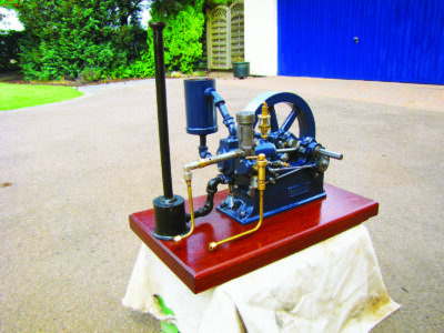
Half-Scale Gardner Model 0 Build
- Manufacturer : Alyn Foundry, North Wales, U.K.
- Year : N/A
- Serial No. : 2292
- Horsepower : 3/4hp @ 450rpm (full-size engine)
- Bore & stroke : 1-3/8in x 2in
- Flywheel : 9-1/2in
- Ignition : Hot tube
- Governing : Volume
- Cooling : Tank-cooled
- Weight : 39lb

The kit of parts included two cut gears, with the only work necessary being to drill and tap the smaller gear for a lock screw above its keyway. The main gear was mounted on a bronze bearing mounted on a shaft fitted to the engine block. A spiral oil groove was cut in this shaft to help lubrication. The stub for this shaft fitted in the engine casting and it was turned 0.037 inches off-center, thus providing a means to adjust the backlash and the degree that the two gears meshed.

The two eccentric straps were machined from the supplied castings and their holding discs were turned from 1.125-inch-diameter steel, with the hole for the shaft offset by 0.125 inch. These holding discs were fitted either side of the main gear wheel, and all shared the same bearing.
To complete these eccentrics, pushrods were made threaded at both ends with connecting eyes made for one end of the rod. The pushrods were made fractionally longer than the plans to provide plenty of scope for them to be trimmed and adjusted after assembly. This would take place when viewing their operation when setting the valve timing.
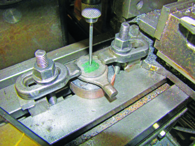
To shape the pivot rod eyes, filing guides were made, namely a narrow disc of steel turned to the radius needed at the end of the eye. A stub on the disc fitted the lateral hole in the eye. For repeat operations, these guides could be hardened for durability, but this step was not taken for this “one use” application.

To finish the eccentrics and gears, the casting supplied for the gear guard ring was machined to fit. This was a delicate piece of cast iron and had to be fully supported during all stages of its machining operations to prevent accidental breakage. The final step was to hold this guard in position in order to use it as a guide to drill the two holes for its securing screws.

Governor and rocker arm
The governor consists of a mount and a rocker arm connected to one of the eccentrics by a pushrod. The trigger block provided a method of adjusting the engine speed using thumbscrews and a tension spring. The rocker arm acts on both of the two inlet valves for gas and air. The trigger block acts to tip the gas valve trigger if the engine is running too fast, thus preventing it from opening the gas inlet valve.

The rocker arm parts were made to plan, but the two mounting holes for the bracket in the main casting were not to be drilled until the engine had been assembled in order to locate their correct position. Furthermore, the valve rocker face and the stub that aligns the gas inlet trigger were not finished, as they would need to be adjusted with a file post assembly by monitoring the action of and positioning of these parts.

To fit the support bracket for the valve rocker, the rocker arm was fitted to it using a bolt as a temporary pivot and it was connected to the inlet eccentric. The valve chest was bolted to the cylinder complete with its valves, and the operation of the valves and governor were checked. The gear was turned to operate the eccentric and activate the gas and air push fingers. The position of the rocker arm support and length of the pushrod were adjusted to achieve perfect operation. As part of this process, it was necessary to file the rest for the gas inlet valve finger so that it aligned with the center of the valve stem. The first hole to mount the rocker support bracket was then marked and drilled in the main casting. Further trial fits then took place to locate the optimum position for the second mounting hole that allowed the support to pivot fractionally and provide a small means of adjustment. The adjustable plate on the gas valve trigger was set so that it worked 0.031 inch behind the air pushrod.

The governor works by the trigger block catching the tail of the gas inlet trigger. If the engine is running faster than the governor speed, the trigger will not have time to reset onto its rest, thus preventing more gas feeding into the inlet box. Fine adjustment is provided by the spring locked by thumbscrews.

Muffler and cooling tank
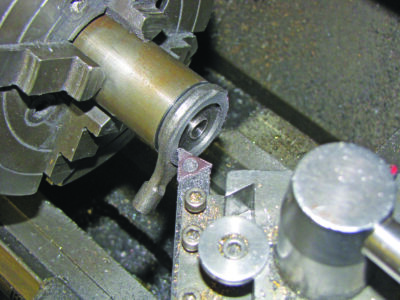
The muffler was fabricated from a length of thick wall tube 2.375 inches in diameter, to which a base plate was welded and a cap fitted at the other end. A 0.250-inch NPT female fitting was adapted to fit the side of the tube and again welded in place, with a further 0.250 NPT thread cut in the center of the top cap.

.
To complete the muffler, a 12-inch length of pipe 0.675 inches in diameter was threaded 0.375 inch NPT at one end and a flared cup was turned to fit the top end of the tube.
After trawling through the scrap bin, a cooling tank was made by first forming then soldering a cup on the bottom end of a piece of 2.750-inch-diameter tube. Two female 0.250-inch NPT pipe fittings were soldered to the side and bottom of the tank to provide water feed to the engine and for its return.
Running in and trial running
For this particular model to work all moving parts must be smooth and easy in operation. It was therefore necessary to turn it over for an hour or so, using an electric motor. This freed it up so that when it was spun by hand and there was no compression, momentum would allow it to carry on turning for several revolutions.

Before starting to use inflammable gas there were some safety considerations. All running would be in a well-ventilated environment, and care was taken to ensure that all valves from the supply tanks themselves were fully closed after each trial. The burner would likely fail to function outdoors in any sort of breeze, so the trials were conducted in a shed, with all the doors and windows open to provide plenty of ventilation.

The original intention was for this engine to be run on small disposable canisters of butane/propane mix. Furthermore, numerous people had suggested that when using gas, it should be supplied through an on-demand valve.
After some research, it was decided to base a valve on the plans of Richard Williams, which can be found on the Florida Assn. of Model Engineers website. This used Tecumseh carburetor parts. Essentially, it blocks the flow of gas to the inlet if there is no vacuum created by the piston sucking the fuel mix into the combustion chamber.
There would be a master cut-off valve/regulator on the gas cylinder before the feed was split, with one line of fuel passing to the on-demand valve before traveling to the inlet chest and the other to the burner. Each supply would be controlled by its own needle valve.
In line with this plan, the on-demand valve, purchased butane burner and small gas tank were joined with brass pipe and various fittings for a trial run using this butane/propane mix. There was an immediate problem, as the feed of gas was insufficient to get a proper flame from the burner to heat the hot tube.
The amount of gas getting to the inlet also appeared wrong, so to simplify testing, the hot tube was removed and a temporary wiper and contact used along with a buzz coil and spark plug to ignite the gas. A spark plug was fitted to a temporary cylinder end cap and a rough brass wiper arrangement made. This was fitted to the crankshaft gear with timing set just before TDC. The theory was that once the gas supply to run the engine had been fine-tuned, attention could then turn to the hot tube/burner.
It soon became clear that the demand valve other engine builders said was essential to run this engine was not activating, as there was insufficient suction/vacuum from the inlet. The valve chest has two valves, one to control the gas inlet that is fed into the air mixer and the other for the air/fuel mix. In effect, this gas inlet valve duplicated the demand valve by shutting off the gas supply unless the engine was at the point of allowing the air/fuel mixture into the combustion chamber.
The general consensus is that the pressure for the gas supply for this engine should be minimal, around 2psi, and the gas inlet valve should be open for only a small proportion of the time when the main inlet valve is open. The level of gas supply is known to be extremely critical; too much being just as bad as too little.
The demand valve was removed from the gas line and a pressure gauge installed to monitor the gas feed. One method to verify the gas content in the fuel mix is to turn on the gas supply and turn over the engine without any ignition activated. The gas from the exhaust should then be lit with a flame, at a safe distance from all body parts and any combustible material. If the mix has a yellow tip to the flame, too much gas is being drawn into the combustion chamber. The ideal is a blue flame.
One way to tune the gas supply is to keep turning the engine, with ignition activated, and starting with the gas supply closed, gradually open it until the engine fires. This was all fine in theory, but there then followed many hours of experiments with different gas mixtures and sizes of gas tank. Different regulators were also used in order to try different pressures.

It soon became apparent that with the purchased needle valves, the adjustment to control the gas flow was too coarse, as there was only a fraction of a turn of the control knob between the engine running and not. This led to the design and construction of a gas control valve, with a small, thin needle and a fine-pitch thread (0.187 inch x 40tpi) for the needle adjustment. By doing this, it was possible to duplicate the shape and looks of an original valve. Using this new control valve, coupled with a propane/butane mix between 1-2psi, the engine fired up using the spark ignition.
Getting to this point was fine, but a gas burner was still needed to produce a hot flame to get the hot tube glowing red. Straight propane worked best with the acquired burners, so the options to run the engine were either use two different gases or change the combustion fuel to propane.

The latter appeared to be the sensible course, so another regulator was obtained to reduce the pressure of the propane. This adjustable regulator worked between 0.75-2.2psi and was fitted after the standard regulator on the tank, which worked in the range of 7-55psi. The feed from the tank would be split before the low-pressure regulator, the higher pressure going to the burner and the gas from the low-pressure regulator feeding into the gas inlet valve.
Gas burner
Once the engine fired using propane as the fuel, attention turned to the gas burner in order that the temporary buzz-coil ignition system could be removed so the hot tube would then become the sole source of ignition.
The burner for the hot tube required a nozzle assembly as well as a control/adjustment tap. The construction plans suggested that a specific burner (9mm Primus No. 8842) be used, but this appeared a little cumbersome and an alternative would be sought. The tip of the burner nozzle would have to fit the horizontal hole to the hot tube burner and provide a hot enough flame to make the tube glow orange-red.
A temporary feed pipe was rigged to a propane gas tank/regulator and a number of different combinations of air hole size and nozzle shape/length were tried, but did not give a clean blue flame, a yellow tip indicating that there was too much gas. The smallest drill available to make a new jet was ten-thousandths of an inch, but this was too big. Fortunately, it was found that the jet in an old Sievert burner appeared smaller, and more importantly, it worked. A brass fitting was made to hold this jet and to allow both a nozzle to be screwed on and also provide a thread to connect it to a gas control valve.

There then followed a period of experimentation to find a nozzle that would both fit the hot tube burner and also result in a hot flame inside the chimney. As part of this experimentation, the air supply holes in the chosen nozzle were enlarged and a small adapter braised at the tip of the nozzle so that it would fit the burner/chimney.
In a similar method to the full-size burners, the position of the burner assembly could be moved up or down to heat a different part of the hot tube and therefore advance or delay ignition.
The chimney for the hot tube was at this point as machined from the cast iron casting. If the gas burner provided insufficient heat to get the hot tube hot enough then consideration could be given to fitting a stainless-steel liner in the chimney and/or insulating the chimney using fireclay in order to provide a measure of heat retention.
Painting/assembly
Once the engine had been run successfully it was stripped and all parts, cleaned and prepared for painting. A baseboard was found, sanded and varnished, ready for the painted engine to be bolted to it.
It would appear that the original engines were painted in a variety of colors, with the early ones and more generally painted a slate gray, but engines have also been found with red, blue and green paint. The standard of paint finish on these engines was extremely high. It was decided to paint this engine a deep blue, similar to some full-size engines I have seen.
The first step was to clean up the castings with a small sanding disc before applying two coats of zinc-based primer. This was sanded smooth before a final primer coat was applied. The top coat was hand brushed, lightly sanded between coats to in order to achieve a high standard of gloss finish. Once the paint had cured, the engine was assembled with all bolts and nuts being left unpainted in case the engine needed disassembly later.
The brass fittings for the gas supply were checked over, with PTFE gas tape or a sealant used to ensure all joints were gas tight. To check for any leaks, the gas supply was switched on, then all the joints were coated with gas leak fluid so any leaks would show up with small bubbles. Soapy water works just as well.
Liquid sealant was use in preference to PTFE tape near any components that would be affected if small fibers of the gas tape tore off during assembly and stopped the proper working of components such as valves.

Starting the engine
Starting the engine is straightforward. Turn on the supply from the gas tank and check the regulator settings. If using hot tube ignition, start the burner and wait for the hot tube to get really hot. While this is taking place, all the linkages and other moving parts can be given a squirt of fine oil and the little end needs to be primed. If the engine is going to be run for more than a minute, fill the cooling system.
When the hot tube is more orange than red, slightly open the gas control lever to the valve chest and pull the flywheel from the front of the engine to the back. Keep turning the flywheel and gradually open the fuel lever until the engine starts firing.
This model proved to be a real challenge. Not the construction, but resolving issues with the gas feed and mix, so it was extremely satisfying when the engine finally worked properly.


