


Take One McCormick-Deering Model LA Engine, Combine it With a
Whole Lot of Work and a Healthy Dose of Ingenuity, and This is What
You Get
I have wanted a steel-wheeled tractor ever since I saw a
documentary on the History Channel showing steel-wheeled tractors
plowing the prairie. For some reason they just say
‘tractor’ to me more than their rubber-wheeled
counterparts.
I live in town, so there isn’t any room for me to restore
(let alone store) a full-sized steel-wheeled tractor like a Fordson
or McCormick-Deering. Instead, I decided to build a smaller version
of the real thing rather than not have one at all.
An electrician by trade, I have a love of all things mechanical.
I have water-cooled hit-and-miss engines as well as some antique
air-cooled engines. I received formal training in various
engineering disciplines while serving in the military, but I am by
no means an engineer. If I have misused or miss-applied formulas or
made other engineering mistakes, I apologize – I simply don’t
know any better, and I welcome all feedback as I feel everyone has
some particular knowledge the rest of us do not.
Calculating the Basics
In 1999 I acquired a 1960 Page garden tractor and restored it.
Restoring the Page was very instructional, as the Page showed me
how engineers can get brute force for plowing from small horsepower
engines. Using the Page to plow a small garden, I learned the value
of gear reduction, increased traction from large diameter rear
wheels,
why a tractor needs independent rear brakes and how a pivoting
drawbar can make up for a small range in drawbar travel for getting
implements in and out of the ground. I tried to employ strengths
and weaknesses I learned while restoring the Page when I set out to
build my tractor.
When it came to choosing an engine, I already had a
McCormick-Deering Model LA 1-1/2/2-1/2 HP engine. I got the LA when
I swapped some parts for building a tractor that I could not use.
After a few repairs, the LA ran so well I knew I had to put it on
something.
Using the Page as a template of sorts, I calculated the rear
wheel torque and speed for all the Page’s three gears. I used
this data, the available horsepower and rpm listed on the LA’s
tag, the gear ratios in the Cub Cadet transmission/differential
unit I chose to use, and the diameter of the rear wheels (31
inches) to figure out the rest of the drive train gearing. I
decided on a 2:1 right-angle gear box in an overdrive configuration
and a 5-inch engine pulley to a 4-1/2-inch gear box pulley to get
850 rpm or better on the transmission’s input shaft. This
combination gave me, on paper, something close to the same torque
at the rear wheel as the Page and the 5 mph road speed I
wanted.
The Page’s Model 19 Briggs and Stratton engine produces
7-1/4 HP at 2,800 rpm for a calculated crankshaft torque of 13.59
foot/pounds going into its transmission. My setup dropped the
calculated 26.26 foot/pounds of torque of the LA down to 11.81
foot/pounds going into its transmission. Comparing the two, I felt
I was pretty well in the ballpark so far.
I calculated rear wheel torque to the ground using the input
torque to the transmission/differential unit, multiplied by the
gear ratios and differential ratio, and divided those numbers by
the rear wheel radius in feet. This gave me a torque to the ground
of 625.65 foot/pounds in first, 315.84 foot/pounds in second, and
149.22 foot/pounds in third gear. Again, this was comparable to the
Page. These numbers give a theoretical drawbar horsepower of 1-1/2
HP. This is in line with the ratings seen on the real antique
tractors, as their drawbar horsepower was usually half the belted
horsepower.
I think people often use their push mower engines as a point of
comparison to the antique engines they see at the shows, and in
doing so they miss-judge the potential they have. Knowing that HP =
torque x rpm/5,252, you can see that for engines of the same
horsepower, the one with the lower maximum rpm will have a higher
torque. This also means an engine of smaller horsepower with
relatively low rpms can produce nearly the same crankshaft torque
as a higher horsepower engine with higher rpms. Tractors need to
pull hard and go relatively slow, so, it would seem to me that
torque is a larger consideration than rpm for this application.
Putting it Together
Construction on the Mini McCormick started on July 1, 2001, and
took the better part of a year. Once I finally got it all together
I ran it and tested it by going up steep hills and pulling around
some of my engines on their carts. Once I was satisfied with my
basic design I disassembled the tractor and painted it. This final
part of the project was completed in June 2002.
I have loosely based the appearance of my tractor on a picture
of a 1928 McCormick-Deering tractor that appeared in the 2001 Old
Iron calendar. In putting it all together, I tried to use parts
that would have been available in 1939 (the year of manufacture for
the LA engine), but I was not particularly successful in that
regard. I was more successful in using a great deal of IHC parts,
which makes it about half International Harvester. Finishing and
painting are my weak points – I intentionally left some dents and
dings in to give it a ‘restored’ look.
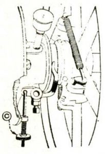
Some parts had to be made, such as adapter hubs for the rear
wheels, fenders and a float bowl for the fuel system. The float
bowl mixer was a factory option on the 3 to 5 HP LA potato digger
model, but not for the 1-1/2 to 2-1/2 HP model. I made a float bowl
that used the original pickup tube and check-ball for the mixer
from an old carburetor that had a damaged throat. I cut away the
throat and venturi and kept the part I needed. This allowed me to
mount the fuel tank above the engine, necessary since the mixer is
a suction type and would otherwise flood.
I also fabricated the clutch pedal, the frame, the drawbar and
linkage, the foot control mounts and linkages, the fuel tank mounts
and hood brackets, and numerous other small parts.
I gathered the remaining parts I needed from salvage yards and
junk shops from Maine to South Carolina. Try finding two steel
wheelbarrow wheels that are the same design and diameter – it
sounds easy until you try to do it. I got lucky and found my two
150 miles apart. That’s part of the fun with a project like
this – that, plus the fun of making something no one else has.
Contact engine enthusiast Chester Leighton at: 1359 Liggates
Road, Lynchburg, VA 24502, or e-mail at: CJL1359@cs.com
The Short List:
Materials for the Making of the Mini McCormick
Rear wheels: IHC manure spreader
Front wheels: Steel wheelbarrow wheels
Front axle, steering box, transmission/differential, disc
brakes: 1978 Cub Cadet 188
Fuel tank: Military surplus, original use unknown
Right angle gear box: Military suplus, used in overdrive
configuration to drive a 20-inch fan with a four-cylinder
engine
Hood: Modified David Bradley walking tractor hood
Steering wheel: 1917 Ford Model T
Seat and spring: IHC horse-drawn two-bottom plow
Drawbar hand lever: Unknown riding lawnmower
Fender skins: Modified trailer fenders from Tractor Supply
Float bowl for mixer: Cut down
Bendix sidedraft: Original use unknown
Frame: Three-inch channel iron Other fabricated parts: Scrap
steel


