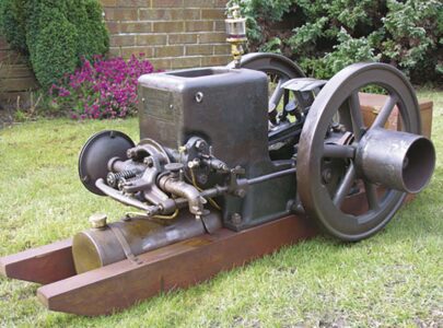
This is the last in a four part series on Peter Rooke’s restoration of a 1917 Fuller & Johnson 1-1/2 HP Model N. Read part 1, part 2 and part 3 for the full restoration process.
Governor

The 1917 1-1/2 HP Fuller & Johnson Model N’s governor latch follower, which rests on the governor ring around the flywheel hub, was badly worn on half of its face. To correct this wear, I ground the underside level and then shaped a piece of steel to fit on the latch before replacing the worn material. I brazed this in place and then ground it to shape so it matched the governor ring on the flywheel.
All that remained of the spring on the latch was a fragment, which helped establish the diameter of the spring wire. The outline of the old spring worn into the pivot helped establish the number of turns, so I wound a new spring using the lathe. It took a bit of trial and error to get the correct adjustment to the arms at the ends of the spring so that the latch worked correctly.


Fuel tank


The Fuller & Johnson needed a new fuel tank, so I followed dimensions provided by Nick Lozzi and cut out some 0.030-inch thick steel sheet. The tank needed to be 16 inches in length, so I cut a sheet width of 16.25 inches, which I rolled to a 5-inch outside diameter with a 0.50-inch overlap at the seam.
First, I needed to prepare a sunk lap seam by forming a 0.50-inch wide recessed strip along the length of the sheet. I did this by clamping a length of 0.0625-inch thick steel to the edge and beating the sheet metal with a hammer to push the metal down around it.
I rough-formed the end caps around a scrap piston that was 5 inches in diameter. To start, I cut out the two discs to a diameter of 6 inches before scribing a 5-inch inner circle. I centered one of these metal discs against the piston and then clamped it tight before using a hammer to start forming it over the lip.


Once the end caps were completed I rolled the body. Not having a roller big enough, I clamped a length of 3-inch round bar to the workbench on top of the sheet. Then I pushed the sheet against the bar to start a curve, but not excessively, to prevent a ridge from forming. I moved the bar and re-clamped. I continued this until the end of the sheet started to close up.
To get the long edges to meet, I tied some rope around the cylinder, then, using the shaft of a hammer through the rope, tightened the rope. I closed the gap until it was possible to fit the two end caps. I marked the positions of the four rivets on the seam and drilled the holes.
I cleaned the holes, then filed the two mating faces smooth and covered them in flux before tinning the surfaces with solder. Then I riveted the edges together and completed the soldering of this long seam.
I also tinned and soldered the first end cap in place. I did not fit the second end cap (closest to the filler) until I completed and placed the various fittings for the tank.
My next step was to make the fittings for the fuel filler and the pipe to the mixer. The latter had a 0.50-inch hole for a slip fit and I added a rubber bung around the pipe to seal it. I made the filler cap and stem from brass, with a 0.750-inch NPT thread. Once all these fittings were completed I fit the second end cap, again soldering it in place after tinning both surfaces.


The final step was to fill the tank with boiling soapy water to check for leaks and also wash out any flux residue. The tank was dry outside with no leaks, so I flushed it out with clean water then gave the inside a small spray of WD-40 and let it dry out.
To hold the tank in place, I cut four straps from 0.050-inch thick steel. These were 0.50-inch wide and bent so that a pair would circle the tank, with tabs that screw to the rails of the skid. I made the bottom one of each pair first so that the tank would be held off the ground, allowing a gap of more than 0.750-inch between the top of the tank and the bottom edge of the cylinder head. Then I rusted the tank, straps and screws before fitting.
I fit the tank and some 0.250-inch brass tube, then I bent it to fit between the tank and the mixer, soldering the check valve to the bottom end of it.
Crank guard

The crank guard for this engine had to be 4 inches wide and nearly 18 inches long. The first step in making the guard was to cut out some 0.032-inch thick steel sheet, 4.5 inches wide and 20 inches long.
To make the two parallel ridges in the guard, I used a 0.250-inch diameter, 2-inch long punch, pressed into a recess of similar profile in a block of cast iron. I clamped a length of steel to this block for the edge of the guard to rest against, acting as a guide. I lined up the sheet metal for the crank guard on the block and then used a hammer and punch to create the ridge, taking care to keep the punch level and not put ripples in the ridge by sliding it along at the same time that it was being hit. I didn’t hit the punch hard. It only took three or four passes to completely form the first ridge, then I turned the sheet around to repeat the exercise and form the second ridge.

I held the bottom end of the guard in place against the engine casting using three tabs, which I formed by cutting and bending the metal. To support the top end, I formed a bracket from 0.125-inch by 0.750-inch steel, twisting the two feet so that the bracket was nearly upright when held on the bearing cap. The height of the bracket above the bearing cap was 4.250 inches. The bend in the crank guard appeared to be a radius of 5.50 inches, so I marked this on the metal bench with a felt pen before bending the guard to this shape by pushing it back and forth over the anvil at the same time I applied light pressure to each side. Then I fit it to the engine so that I could adjust the lower tabs and curve it to fit tightly against the engine block and be clear of the moving crankshaft/connecting rod.
My next step was bending some 0.250-inch steel rod to a tighter radius than the guard and then welding the rod to some scrap steel so that I could use it as a former to roll the edges using a light hammer.

I held the former in a vise and moved the guard along it, while at the same time tapping the metal with a clean-faced hammer to bend it. When satisfied with the rolled edges, I again checked the profile to the engine before marking the position of the two 0.250-inch holes for the rivets that hold it to the bracket. I drilled these holes and held the guard in place so that I could transfer their position to the bracket and then drill. Finally, I hammered in the rivets.
In its present condition the guard looked too new, so I gave it a washcoat of dark green paint. After the paint dried, I sanded the high spots, edges and other likely areas of wear to expose bare metal. Then I aged the paint by heating it. Using a clean flame such as propane is no good, so I used a dirty flame, in my case a candle. This darkened and dulled the paint. Then I dipped the guard in water and left it, allowing rust to form.
Oil tray

A lot of old engines are missing their oil trays, which sit inside the casting. I am always conscious about fouling a show site, and making and fitting a tray catches a lot of the oil flung around by the engine. I place a can underneath the engine’s drain hole to collect the oil.
I cleaned paint off a piece of scrap sheet before cutting it to size and forming raised edges. I formed a crease down the middle of the tray to funnel the oil to the drain hole. The tray rests on the wood of the sled with the raised section fitting underneath the cylinder.
Skid
Since I left this restored engine in its original work clothes, new wood on the replacement skid would look completely out of place. I cut some new timber to the dimensions supplied by Scott Barnes, using some timber that had splits in it to add to the “old” look.
I experimented on an off-cut with a few processes to get the best results on the soft wood I had.

It is not too difficult to age new timber with materials found at home to give a realistic finish. There are some commercial solutions available but the natural solutions used — in this case tannins and iron — give good, if not better, results. For example, staining with tea tannins gives a less-even coating than a wood stain and does not seal the wood.
As there were traces of original red paint on the engine the new skid would have traces of red paint used on original skids, using dregs from an old rattle can to give it a light dusting.
The next step was to distress the wood to give the appearance of a hard life. I used coarse sandpaper to remove paint, paying particular attention to the ends of the skid and the outer sides along with other areas that would have taken the brunt of wear, such as around the gas tank. I only lightly wiped the insides of the sled as well as the area of wood protected behind the flywheels. I removed (or scored) the layer of paint so the aging process could work effectively on the fibers of the wood.


The second stage is the distressing of the wood to try and create the appearance of years of use. I removed the clean new edges of the prepared timber and gave them a few dents and scrapes. This involved hitting it with chain, iron bar and steel pipe to give different sized and shaped scratches and dents. Again, I paid particular attention to the ends of each skid and the outside edges.
Some woods are high in tannic acid, like oak, walnut and mahogany, but for wood with low tannic acid, such as pine, the level needs to be increased to react with and assist the working of the other compounds used in the aging process. The first step is to coat the wood with a solution of strong tea, which will impart a mellow tone to the wood. Either make strong dark tea with boiling water and allow it to cool a little so that it can be brushed on or, the messy way, soak some tea bags in hot water then rub them along the wood, ensuring that the bottom of any cuts and gouges are covered. The mixture does not have to be hot to work, so you can store it for a few days.
The second step, when the wood is dark enough from the staining, is to cover it with a ferrous acetate solution. You can easily make this solution by breaking up some pieces of very fine steel wool and covering them in white vinegar for at least 24 hours. The container does not need to be air tight and it is not necessary to cover all the steel wool with the vinegar. The majority of the steel wool will dissolve in the vinegar, and then you can siphon off the liquid from the sediment or filter it through paper towel. Then you can brush on the ferrous acetate.

When you apply the ferrous acetate solution, the wood will react with the tannic acid and produce a non-fading gray color, in some cases almost black. After applying one coat let it dry thoroughly, preferably in hot sun, and give the tannic and ferrous coats plenty of time to react. The treatment of the skid shown took place over two weeks and received several coats of the ferrous acetate solution.
The final step was to bring the wood to life with some old, black oil. I applied this more thickly to the area around the flywheels and the back end of the skids. To assist this part of the process, I played the propane torch over the wood, taking care only to heat the wood and not singe it.
I had the dimensions of the battery box and used some old wood to make it, joining the corners with round head nails, just like the original. I prepared a stencil on the computer to match the original letters, which I cut out and then fixed to the box before spraying with matte black paint. I also distressed this box in the same manner as the skid, with any iron work being rusted with a gun browning solution.
The final step after creating these replacement parts was to stamp my initials and the date out of direct sight so they could not be passed off as original.


Gaskets
The old cylinder head and igniter gaskets were made from 0.0625-inch thick copper. The old gaskets still looked serviceable but I made new ones. I made them by marking a sheet of copper with the outline of the old gaskets before cutting and filing to shape.
Assembly and starting
Assembly presented no problems. I timed the igniter to trip when the piston was at 18 degrees before top dead center and the exhaust valve to open at 40 degrees before bottom dead center and to close some 10 degrees after top dead center.
Ignition is through a 6-volt battery and coil in the new battery box. This engine was originally fitted with a magneto, evidenced by the metal ring on the igniter side of the water hopper to support the wire from the magneto to the igniter. At the time of writing, I have just purchased a small Sumter magneto with the intention of making a bracket and gear wheel for it as a project next winter.

No starting wrench arrived with the engine and the belt pulley inner boss was profiled to provide a starting lug. I made a starting wrench from various pieces of steel in my scrap bin to match this lug.


After checking that all nuts were tight, I greased and oiled the engine before adding fuel. I filled the drip feed oiler and initially set it to 10 drips a minute to fully lubricate the repaired piston. While choking the mixer, I turned the engine over after switching on the battery/coil. After a few turns it coughed and started to run a little fast. After it had warmed up a little, I adjusted the governor so that it was working around 400 revs, plenty fast enough for demonstration purposes. Care is needed when starting the engine, as it floods easily if the needle is not carefully set, perhaps in view of its relatively steep taper. I found that the choke only needed to be closed to prime the engine, then set half open until the engine ran. I ran the engine for several hours over a couple of days, keeping it well-lubricated to bed everything in. I checked and tightened, if necessary, all nuts and examined the repairs for signs of any problem. All appeared well.

Another restoration completed, the engine having a well-worn, no nonsense look, still in its working clothes.
Contact Peter Rooke at Hardigate House, Hardigate Rd., Cropwell Butler, Nottingham, NG12 3AH, England • peter@enginepeter.co.uk • www.enginepeter.co.uk


