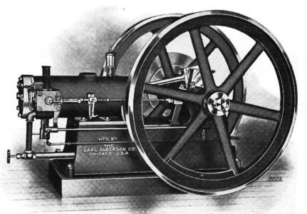
- Manufacturer: The Carl Anderson Co., Chicago, IL
- Serial no.: 232
- Horsepower: 2 hp (est./rpm unknown)
- Bore & stroke: 4-1/8 in x 6 in
- Flywheel dia.: 22 in x 2-1/2 in
- Ignition: Igniter (originally; converted to spark plug at unknown time)
- Governing: Throttle governing
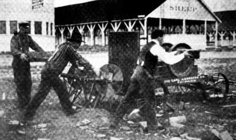
I first met Gus back in 1971, when my wife and I were vacationing in Maine. Driving through the village of North Windham, I spotted a likely place where I might find old engines and wheeled around. There, we met a friendly gentleman who had several engines, including Gus. He had painted a few, but had no interest in running them. After chatting a while, he agreed to a deal and Gus was mine. We returned a few months later with the old International pickup and loaded him up. We got back home not only with Gus, but also with a 5hp Otto and a 2hp Buffalo marine engine in the truck bed! The Otto now powers a triplex pump in the Pump House, and the Buffalo is displayed in the Susong Building.
Sadly, I did not understand Gus – he just didn’t make any sense on how he could have operated! The Otto and the Buffalo marine were put on display in the museum, but Gus was stored in the old garage to wait for a day to live again. Forty-five years later and perhaps a bit smarter – and with the help on the Internet – I learned what a complex and wonderful engine Gus is. Despite his metallic blue paint and white flywheels, he is now in my shop, being prepared to live once again.
Background
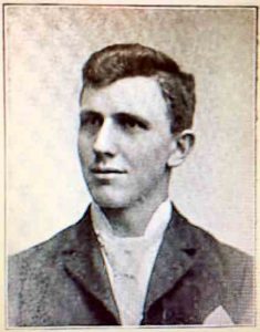
Gus’ designer was a young Swedish immigrant named Gustaf Joranson, hence Gus’ name. Joranson is shown in Photo 2. Joranson was born on March 13, 1868, in Nykroppa, Vermland, Sweden. Receiving a common school education in his homeland, he then came to Chicago in 1887. In 1888, he worked for A. Schauble & Co. as a machinist. He soon transferred to the Carl Anderson Co., where he conceived and received his engine patents and built Gus. Anderson was also a young Swedish immigrant, and one wonders if they knew each other back in Sweden?
In 1893, Joranson married Hansine Amundsen Hansen, a Norwegian immigrant. They had four children and lived at 5346 West Ohio St. in Chicago, and the building they lived in still stands and can be seen on Google Maps. Joranson was naturalized in 1896. In 1900, he was listed in the Chicago directory as a gas engine salesman. Interestingly, he disappears from all records in 1918, and one can only wonder if he fell victim to the great flu epidemic of that year.
Patents
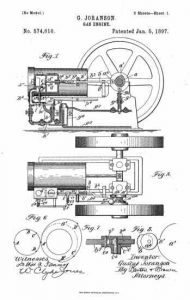
Joranson had two patents on his engine design, the latter assigned to the Carl Anderson Co. His first patent, number 574,610, granted on Jan. 5, 1897, basically had all the features of the engine I had, but not yet in a practical design. That patent is shown in Photo 3 and is th patent date that is displayed on Gus’ nameplate. The second patent, number 740,571, granted Oct. 3, 1903, shows the exact engine as it was built. This patent was most useful in helping me understand how Gus actually runs. The second patent in shown in Photo 4.
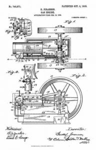
A 1902 advertisement for the Gus engine shows an engine identical to that described in the 1903 patent, but published a year before the actual patent. The ad’s tagline is “The best is none too good.” Note the excellent proportions, great workmanship and fine lines, making a very pleasant looking engine. The engine shown is identical to the 1903 patent..
The Coolspring Gus
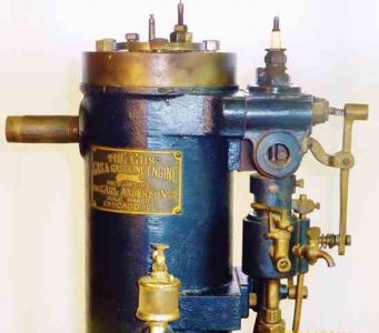
The Gus living at Coolspring is a vertical model, and it is essentially the same engine shown in the 1903 patent, but rotated 90 degrees. It is similar in all its mechanisms, which are very unique.
Basically, the engine is a 4-cycle, throttle-governed design with a ported cylinder. Gus’ cylinder bore is 4-1/8 inches and the stroke is 6 inches. There is one eccentric on the crankshaft and no timing gears. A pressure operated device on the valve chest senses compression pressure and engages a lever that activates the exhaust valve. It is governed by a “pork chop”-like weight in the flywheel that limits the stroke of the intake valve, hence the throttling governor. The electric igniter is piston tripped, eliminating any outside mechanism.
The only mention of electric ignition that I discovered was found in a 1905 Modern Machinery article, which noted that, “The engine is equipped with both hot tube and electric igniters, which enables it to run in all sorts of weather.” All other illustrations show just a hot tube mounted in the intake valve cap.
As I studied Gus, I pondered how this could possibly work successfully. Then I looked at all the carbon deposits inside Gus, and all the wear on his parts, and realized that it had worked well for many years. Now to see how this all fits together.
Construction
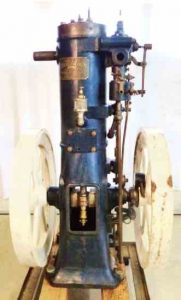
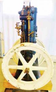
Photo 6 is Gus’ front side. The base and cylinder are all one casting, which required extensive machining for all the parts to be in alignment. This overall profile is similar to other vertical engines built in Chicago. The pipe to the left below the cylinder head is the cooling water outlet. The water enters the lower part of the cylinder on the other side, circulates up through the head, and exits here. The nicely finished brass connecting rod sports a grease cup. Photo 8 is a side view. The flywheels are in nice proportion to the rest of the engine. The cylinder oiler is in plain view.
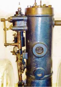
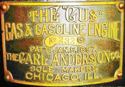
Photo 9 shows the rear of the engine.The water inlet is at the base of the cylinder, and the large exhaust port dominates the back side. The valve chest appears on the top left, and the exhaust from the valve is ported through the cylinder to the main exhaust port, further complicating the casting design. The lever that engages the exhaust valve can be plainly seen.
Some of the details of the cylinder head and the piston-tripped igniter are visible in the photos. The igniter is not complete on the inside. The intake valve cover now has a spark plug, which was a later modification. This would have been the location of the hot tube, if so equipped.
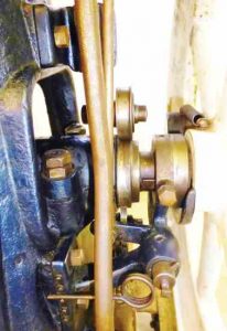
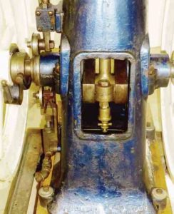
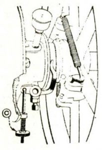
Photo 10 is a detail of the valve chest, the pressure operated exhaust valve latch and the gasoline overflow bowl. The governor rod reaches up to here and controls the tension on the intake valve spring, hence regulating engine speed. Not present on the photo, there would have been a 3/4-inch pipe that entered the intake valve opening and turned downward. A tiny pipe would have entered its side to admit gasoline into the upward air flow. This primitive “carburetor” was typical on many early engines and worked well. Photo 11 shows the one large eccentric on the crankshaft and the large exhaust valve roller above it. The governor is on the flywheel and a large torsion spring can be latched into several pegs to adjust the engine speed. Finally, Photo 12 shows the fuel pump, which supplies a continuous amount of gasoline to the overflow bowl.
Gus is, indeed, a unique and complex engine. He will be proudly displayed at our 2016 Expo, June 16-18, when the feature will be “One-of-a-Kind” Engines. Next issue, we’ll visit Gus’ maker, the Carl Anderson Co., and its successor, W.C. Anderson Co.
Paul Harvey is the founder of the Coolspring Power Museum in Coolspring, Pennsylvania. Contact the museum at PO Box 19, Coolspring, PA 15730 – (814) 849-6883


