The following article is by the courtesy of Edward L. Fleming,
1027 Meadowbrook Road, Iola, Kansas 66749 and he states: ‘This
is a copy of a gas engine timing instruction sheet distributed by
Kansas State College (now Kansas State University) about 1935.
These instructions were given to me by my uncle who was a
vocational agriculture instructor. I thought it might be helpful to
a lot of your readers.’
PURPOSE: To give a definite procedure for
checking the valve and ignition timing of a single cylinder gas
engine and for retiming if necessary.
EQUIPMENT: Rule and string, or tape, wrenches,
pliers and tram.
EXPLANATION:Farm gas engines are generally of
the four-stroke cycle principle and use valves to admit and exhaust
the fresh and burned gases. Contrary to the belief of many, the
valves do not open and close at the ends of the strokes, but vary
from this as much as 45 degrees. A timing that gives maximum power
and best operation is determined experimentally for each engine,
and used. Naturally, therefore, the exact time at which the valves
should open and close, varies with engines of different design. If
the manufacturer’s instructions are at hand they should be
followed. The following suggested timing is average for small
engines running between 400 and 600 rpm and will give good results
where the exact timing is not known:
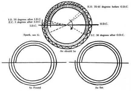
Exhaust valve open – 35 degrees to 45 degrees before ODC on
power stroke. Exhaust valve close – 5 degrees after IDC on intake
stroke. Inlet valve open – 10 degrees after IDC on intake stroke.
Inlet valve close – 30 degrees after ODC on compression stroke.
(NOTE: Inlet valves are usually automatic; above applies when they
are mechanically operated.)
From the above, the range of opening can be calculated. It would
be from 220 degrees to 230 degrees from the time the exhaust valve
opens until it closes and for the inlet the range is 200 degrees.
The range is adjusted by the tappet or screw on the rocker arm and
it is absolutely necessary that this range be correct before the
valves can be timed accurately.
In running position the spark should be made to occur before the
end of the compression stroke, the number of degrees before
depending upon the speed of the engine. It is necessary to allow
some time for the gas to burn and reach a maximum pressure at the
IDC or beginning of the power stroke.
PROCEDURE:
Determine Range of Value Operation. [Tappet Adjustment] On small
farm gas engines it is impractical and valueless to attempt to give
any definite figures on valve clearance. The clearance is set
indirectly by adjusting the range.
1. Measure circumference of flywheel. 2. Calculate number of
degrees per inch. 3. Check points where valve opens and closes,
mark on flywheel. 4. Measure distance between points and convert to
degrees. 5. If correct, make no adjustment, if not correct, proceed
as follows. 6. Adjust by screwing in or out the screw on rocker
arm. 7. Screwing in increases range, out decreases range.
Locate Dead Centers
Inner dead center (IDC), head dead center (HDC), or top dead
center (TDC) in vertical engines have the same meaning. Outer dead
center (ODC), crank dead center (CDC), or bottom dead center (BDC),
in vertical engines have the same meaning.
Turn flywheel until piston is near inner or outer end of its
stroke.
Find some fixed point such as the back or outer edge of the
cylinder wall with which the skirt of the piston will just come
flush when near the end of the stroke. On enclosed engines or where
such a point cannot be found it may be necessary to measure in to
the piston head through the spark plug hole, or a rule or other
measuring device may be placed against the piston from the rear
end. Note the distance from any fixed point to the head or rear end
of the piston. Remember this measurement is made with the piston
near either dead center.
With engine in this position, place a mark on the flywheel,
using tram or pointer.
Turn flywheel in direction of normal rotation until piston again
coincides with fixed point or measurements taken in step 2.
With engine in this position, place another mark on flywheel
with tram.
Measure halfway between these two points on the flywheel and
place a third mark. This is IDC or ODC, as the case may be, and the
engine will be on exact dead center when the tram registers with
this point.
Erase the first two marks.
Measure halfway around the flywheel and there locate the other
dead center ODC or IDC, as the case may be.
Check Valve Timing
Measuring from the dead center marks, locate on the flywheel the
correct timing marks and label clearly; e.g.; EC (exhaust open) -EC
(exhaust close).
Turn the engine in normal direction and locate on flywheel where
valves do open and close, using tram.
If those marks coincide with the correct timing, no further work
is necessary on the valves.
Timing Cam Gear
If found out of time in part C, the cam gear must be retimed
with relation to the crankshaft gear.
Dividing 360 by number of teeth in crankshaft gear will give the
degrees change caused by shifting the cam gear one tooth.
Estimate or measure degrees and number of teeth on cam gear, the
valve is out of time.
If valve opening is late, move cam gear forward in normal
direction of rotation the right number of teeth; if valve opening
is early move cam gear in reverse direction the right number of
teeth.
Remesh timing gears.
Inlet Values
Inlet valves are commonly automatic on farm gas engines and are
not timed. The springs may become weak. A weak spring may be tested
by inserting a screwdriver under the spring and increasing the
compression a little while the engine is running, under load if
possible, and observe the speed and power of the engine. If the
engine gains in speed and power it is an indication the spring is
too weak and a new one should be installed.
Check Ignition
If spark is adjustable, set advanced or in running position.
Rotate flywheel in normal direction and locate on flywheel
position of spark.
Measure, convert to degrees, and compare with correct
setting.
Timing Ignition
Study engine to determine easiest method of shifting spark.
Where the exact setting is not known, a simple rule to follow is
to allow 5 to 7 degrees of advance for each 100 revolutions per
minute of the engine. The greater number should be used with
engines using low-tension igniters than when using high-tension
systems and spark plugs.
Adjust igniter trip or timing device to cause spark to occur at
correct time.


