PO Box 832, Prentiss, MS 39474, all rights reserved
The modern dry cell battery is a marvel of technology combining
power and durability into a relatively compact, inexpensive
package. Unfortunately, its ability to provide reasonable service
in ignition applications is sometimes misunderstood.
Misunderstandings can promote misuse and lead to poor performance;
the end result is the battery often receives an underserved
reputation for general unsuitability. In defense, a battery (like
any other device) cannot be expected to give optimum service beyond
the limits of its design. However, ignition operation within these
capabilities is possible. Hopefully this article will enable the
restorer to recognize the capabilities of dry batteries and correct
problems that can be encountered in their use.
To illustrate some of the variables involved in battery design
let’s investigate the NED A (National Electrical Distributors
Association) 918 series: a 6 volt ‘lantern’ style widely
available from several manufacturers, and often used for hit &
miss engine operation. Specifications for three variations of the
NED A 918 offered by ‘Eveready’ are given in Table
‘A’. Note that the current ratings for the various
configurations range from to 1 amps. Also be aware of how
temperature affects these batteries. High temperature raises output
but speeds up deterioration due to increased cellular chemical
activity. Conversely, cooler temperatures improve storage life but
decrease output. Carbon-zinc types suffer the most from temperature
extremes; zinc chloride is better; with alkaline models being the
least effective of the lot.
Batteries under consideration for ignition use must possess the
ability to adequately handle the drain imposed by the intended
system. Fresh dry cells are capable of brief outputs well
in excess of their rated current levels and will recover from such
excursions if allowed to ‘rest’. However, repeated use at
elevated drains will eventually lead to failure. How soon failure
occurs is hard to predict. Chemical makeup, age, storage/operating
temperatures, duration of high-level drain, and ‘rest’
interval, all enter into the picture. Abuse of any, or a
combination of these factors can lead to a disappointingly short
service life. Knowing the operating parameters for these batteries
is helpful, but more needs to be known about the power requirements
of the ignition device itself before a determination of suitability
can be reached.
High current drain caused by ignition equipment with inherently
low resistance is probably the chief factor in many cases of early
battery demise, Automotive ignition coils were designed to operate
in conjunction with power supplies capable of furnishing very high
current. But even under such circumstances, some type of internal
or external resistance was utilized to limit current flow. Used
without a resistor, an automotive coil will wreak havoc on a dry
cell. ‘Buzz’ type coils are also current hogs, and a
significant amount of power is required merely to operate their
magnetic vibrators. Even ones designed for small engine service
were often originally intended to use four or five 1 volt
high-current ‘ignition’ cells in series. Restorers desiring
to use a 6V lantern battery with these types of coils may wish to
experiment with a current limiting resistor of between 2 to 5 ohms,
rated at 20 watts minimum. Insert the resistor in series between
the coil and battery the objective being to raise system resistance
and thus reduce current flow to a level within the battery’s
capability. Low-tension coils can also pose a problem: most
requiring fairly high current, again due to low internal
resistance. Select a coil specifically designed for low current
drain (6 to 10 ohms internal resistance) as external limiting
resistors are not recommended with low-tension systems.
Best battery life is seen on very slow turning engines
(particularly those with some type of ignition cutout governor),
since ignition ‘on’ cycles can be as few as 5 to 10 per
minute. Service can be further enhanced by insuring that contact
dwell during these ‘on’ cycles is of no longer duration
than necessary to provide adequate ignition. Remember that dwell,
though measured in degrees of rotation, is really an expression of
time. A coil requires a given amount of time to respond no matter
what the engine speed, so manufacturers originally specified enough
dwell to cover ignition needs at the highest anticipate a RPM. When
operating at low RPM, longer dwell is just ‘icing on the
cake’, and serves only to decrease battery service life.
Dwell is particularly important on low-tension igniters. Some
systems were designed to have the points in a closed position
between firing cycles; while others allowed the points to remain
open until just before ignition. A few manufacturers provided a
means of selecting either mode of off-cycle point disposition
depending upon whether a battery or magneto was used. One example
is the Associated Manufacturers Company which gave the following
instructions on igniter setup: (The igniter points should
separate about 1/6′. When operating engine on batteries the
igniter points should be held apart by a small coil spring attached
to the igniter hammer stop and the left hand post on igniter body.
Either ‘open’ or ‘closed’ position of igniter
points can be used for operating engine on magneto.) In 1913
directions for their engines, the International Harvester Company
recommended igniter points be set to dwell closed for about 60
degrees of crankshaft rotation prior to opening, and cautioned that
less dwell might not allow adequate time to properly energize the
coil. International’s figures were based on an operational
speed of 400 RPM experimenting with slower speeds and different
coils might well yield satisfactory operation at less dwell on your
particular engine. If the system is not adjustable, you may wish to
fashion some type of cutoff mechanism to prevent battery drain
during off-cycle operation. A sketch and description of such a
device appears in the December 1985 issue of Gas Engine Magazine on
pages 20 and 21.
TABLE ‘A’ | |||
‘Eveready’ | 731 | 1231 | 521 |
number/name | Lantern Battery | Super Heavy Duty | Energizer |
type | carbon-zinc | zinc chloride | alkaline |
voltage | 6 | 6 | 6 |
max. suggested | 1/2 amp | 3/4 amp | 1? amps |
prolonged high | fair | good | very good |
output ability | |||
cost | low | moderate | more expensive |
Characteristics of three NEDA No. 918 series ‘Eveready’ | |||
Courtesy: Battery Products Division of Union Carbide | |||
Though a declining battery is often capable of furnishing
extended service at very light current drains, the inability to
provide output at or near rated levels is an indication of general
weakness. A battery in this condition may give erratic or
unsatisfactory performance. Weakness (brought on by age, high
temperature, or high current drain) is a result of chemical changes
within the battery. Chemical deterioration causes a rise in
internal resistance; eventually to a point that restricts voltage
output, particularly at high current drains. Oddly, there is very
little difference in voltage readings between fresh and depleted
cells on open circuit. So accurately judging the present condition
of dry cells requires that measurements be taken under load.
Equipment designed for such testing is available, but beware of
inexpensive models as they may not expose the battery to enough
load to be of use. For example: ‘Eveready’ recommends that
a 6V lantern battery be tested with a load of 5 ohms, but a
multi-battery tester sold by Radio Shack gives about 600 ohms on
the six volt setting. Since higher resistance means lighter load,
the 5 ohm test will give a much better indication of a
battery’s suitability to high-drain ignition use. Obviously a
questionable battery could receive satisfactory rating on a 600 ohm
test, yet fail at 5 ohms.
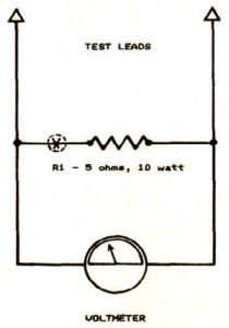
Figure ‘A’ shows the schematic for building a simple
device to correctly load test lantern batteries. The tester is for
use on 6V dry cells only (though it can be used for comparative
purposes on 6V storage batteries) do not use it to test units rated
at over 6 volts. R1 is a 5 ohm power type resistor with a minimum
rating of 10 watts. If such a resistor is not available, wire two
10 ohm, 10 watt resistors (Radio Shack no. 271-132; priced at two
for $.89) in parallel to give 5 ohms, 20 watts. If you already own
a multimeter, all that is required is to solderR1 between the test
leads (you may want to add alligator clips to a separate set just
for battery testing). Connect the leads so as to place the load
(R1) across the battery terminals, and read voltage output. Be sure
to observe proper meter polarity and keep test periods brief since
the load is rather severe. More accurate readings will be taken
with the meter set to indicate at half scale or higher. To evaluate
a battery, compare reading with the following percentages of rated
voltage:
0.0-61% (0.0V-3.66V)replace
61%-72% (3.66V-4.32V)weak
72%-105% (4.32V-6.3V)good
Bear in mind that these readings reflect general battery
condition and do not necessarily indicate it to be fit or unfit for
service. A system with inherently low current needs can often
function on comparatively weak batteries, while a less efficient
device is rendered inoperable.
A more versatile arrangement would be to mount a 0-8 DC
voltmeter and R1 in some type of enclosure. Locating a momentary
push button switch at position ‘X’ in the schematic will
allow for taking readings with or without a load. This can be
useful in determining the compatibility of the battery with a
particular coil. For instance, suppose you have determined a
battery is good by testing it under load with the switch closed;
you can then substitute a coil for the load resistor by temporarily
connecting it across the battery and observing the meter reading
with the switch open. If the reading falls in the weak or replace
range, then the coil will likely overdraw the battery. Following
these basics will enable you to get all of the inexpensive, trouble
free service that a dry cell battery can provide. Remember:
Buy a battery known to be fresh.
Store it in a cool place.
Operate it in warm surroundings.
Keep drains within specifications.
Good luck!
Those desiring more information on electricity, ignition and
batteries, may wish to read a book by the author entitled: Make and
Break Ignition Manual available from LoneOak Distributing Company,
PO Box 832, Prentiss, MS 39474 for $9.95 ppd.


