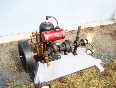
Circa-1907 Grasser marine
- Manufacturer: Grasser Motor Co., Toledo, OH
- Serial no.: None marked on engine
- Horsepower: 2-1/2-3 hp (est.)
- Bore & stroke: 3-1/16 in x 3-1/4 in
- Flywheel dia.: 12 in x 2-5/8 in
- Ignition: Spark plug w/battery and buzz coil
- Governing: Throttle


In 1995, an acquaintance of mine acquired a 1-cylinder, 2-cycle Grasser marine engine made about 1907 by Grasser Motor Co. in Toledo, Ohio. Very little is known about the company; even C.H. Wendel’s American Gasoline Engines Since 1872 shows Grasser in the index only. I acquired the engine in 2014 and decided to get it running again, but not cosmetically restore it. It’s not rusty or scruffy, and has very good paint on it, possibly the original, and a very heavy-duty looking clutch.
Missing parts
The piston and connecting rod were missing, but I thought I could find a piston from a small engine that would fit. However, it seems very few engines used a 3-1/16-inch piston, and one I did find, the piston was no longer available. A decision was made to carve one out of a round billet of cast aluminum, which I bought from my local metal supply store, 3-1/2 inches in diameter and 5 inches long. In the July 2005 issue of GEM, the late Glenn Karch wrote a good article about machining an oversize piston to fit a worn cylinder in one of his Hercules Engines. His was a little easier to do as he had a piston to copy from; in my case, I had nothing to go by!


I reread his article and gained some insight into how to set up the lathe and mill. I started by honing out the cylinder so as to get it as smooth and round as possible. This is a headless, dome-top engine, so all the work is done from the bottom end. As a starting point, I mocked up a piston from pine wood, 1/2 inch thick, 3-1/16 inches wide and 3-1/2 inches tall with a 3/4-inch wrist pin hole drilled in it 1-3/4 inches from the top. I glued a 3/4-inch wood dowel into the wood pattern, then using two pieces of a broken wooden yardstick I made a simple pattern to use as a jig for measuring the connecting rod.


The jig has two vertical slots cut in it 3/16 inch wide for making adjustments. The two pieces are held together with a machine screw and nut and washers. This is to get the correct length of the rod when the engine is at bottom-dead-center. In this 2-cycle engine, the intake and exhaust ports are directly across from each other. At bottom-dead-center the piston crown has to be just below the ports for the engine to breathe. I installed the wooden piston pattern in the cylinder bore so the top of it was just below the ports. I looked in the exhaust port with a small flashlight to make sure it was in the right spot and locked it there with a wooden wedge. Next, I installed the crankshaft, positioned at bottom-dead-center, and adjusted the sliding yardstick pattern so it touched the crankshaft journal. I now had the needed connecting rod length, 6-11/16 inches.


The next step was to make a fixed pattern of the connecting rod 6-11/16 inches long. To get the top-dead-center piston mark, I made an “L” shaped marking pencil from a piece of carpenter pencil lead 1-1/2 inches long, glued together at a 90-degree angle using a 1/4-inch dowel and 5-minute epoxy. The stroke was 3-1/4 inches. Stuck down the spark plug hole onto the top of the wooden piston pattern, it put a mark on the cylinder wall to indicate top-dead-center.


This engine has counterweights on the crankshaft much like an automobile engine, a very modern design for the early 1900s. To make sure the new piston did not hit the counterweights, I drilled a 1/4-inch hole in the bottom of the wooden piston pattern and put a 1/4-inch dowel in it sticking out 1-1/2 inches, then I turned the crankshaft over to see how much the dowel cleared the counterweights and cut it to length. The finished piston would be 3-7/8 inches tall and 3-1/16 inches plus 0.020 inch in diameter.
Making the piston
Most likely the original piston was cast iron. The aluminum blank I bought had been rough sawn on a horizontal band saw and had to be squared up on one end and then turned down for a 3-inch lug on the other. The lug would go in the lathe chuck, with a live center supporting the tail end. Machining the piston outside diameter and cutting a small relief where the rings go was easy, but cutting out the inside of the piston was a slow and tedious process: I had to make three cutting bits for this and one to cut the ring grooves.


To machine the inside of the piston, I drilled a hole into the middle of the piston, starting at 3/8 inch and ending up with a 1-1/8-inch hole. This allowed me to use a long end mill to cut around the wrist pin bosses and make the relief cut for the connecting rod clearance.
The next step was to drill and ream the wrist pin hole to 3/4-inch. The final step on the piston was to cut the ring grooves. The rings I could get were 3/32 inch wide. I ordered three rings and when they arrived I cut the grooves in the piston. The last step was to drill and tap a 5/16-inch retaining bolt hole in the wrist pin boss to keep the wrist pin in place.
Making the connecting rod
I had previously bought a few miscellaneous connecting rods and pistons, and in this lot I found a connecting rod with a 3/4-inch wrist pin and a 1-3/4-inch big end. The Grasser engine has a 1-1/16-inch connecting rod journal. The rod I used was too wide, so I machined it equally on both sides to size. It was also too long, with an 11-7/8-inch overall length versus the 6-11/16 inches I needed. I cut and shortened the rod, and using my wooden rod pattern as a guide I made a jig to hold the shortened rod halves for welding.


The jig was made up of two pieces of thick-wall square steel tube I had lying around the shop, one piece 1-inch square and the other 3/4 inch square, both cut to 12 inches long. I then made two round steel mandrels, one 3/4 inch x 3 inch for the wrist pin and the other 1-1/8 inch x 3 inch for the crank pin. The crank mandrel was bolted to the welding jig with a 5/16-inch bolt, giving me a little wiggle/adjustment room to get the rod just the right length. With the mandrels bolted onto the welding jig and correctly adjusted, the two halves of the cut and shortened connecting rod were clamped onto the welding jig and then checked for alignment.


Before welding, I preheated the jig and rod assembly in an oven to 450 degrees F and then arc welded them together. Despite a serious effort to keep everything straight in the jig, the welding distorted the rod some and I had to straighten it up a little so that the wrist pin and crank journal were on the same plane.
Babbitt pouring
Babbitt for the new connecting rod needed to be poured. My babbitt pouring jig is a flat piece of 3/8-inch thick steel 2-1/2 inches wide and 20 inches long, with holes drilled in various locations for the mandrels I use. I drilled one of the holes in the jig 5/16 x 18 TPI and bolted the wrist pin mandrel made for the welding jig onto the babbitt jig. I then placed the wood connecting rod pattern over the wrist pin mandrel to give me the placement for the connecting rod mandrel. Another 5/16-inch hole was drilled in the jig and the crank mandrel was installed. However, I needed a smaller mandrel so I would have space for the babbitt, so I made a smaller, 1 inch in diameter crank mandrel.


Next, I took a piece of 14-gauge copper electric wire, formed it into a circle and soft-soldered the two ends together. This was then epoxy glued to the side of the connecting rod that will face the babbitt jig. For lack of Babbitrite or similar damming material I used high-temp automotive silicon gasket sealer to seal and dam up the jig for pouring. This was allowed to set and dry for a couple of days before pouring.
Time to pour! I use an old 240-volt stove top burner for my heat source. For melting babbitt, I modified a 2-inch wide by 2-1/4-inch deep stainless steel ladle, with a “V” notch formed into one side of it for pouring. An old sauce panhandle my wife donated is bolted onto the ladle. The babbitt mold jig is set about 1 inch above the burner element and the babbitt ladle is placed right on the element itself. When the mold reaches 250 degrees and the babbitt in the ladle looks shiny and will char a wood stick, it’s ready to pour.


Before pouring, any impurities floating on the top must first be skimmed off. I use a thin piece of 1/4-inch wide wood for this. After the babbitt is poured, I lightly tap the mold with a small hammer to remove any air bubbles while the babbitt is still liquid. Once cooled, it’s time to machine the inside diameter of the rod bearing. I had to make a tool for this. It’s a 5/8-inch round piece of steel, 8 inches long with a 3/16-inch hole drilled through it at a 45-degree angle 1/4 inch up from the bottom. Another hole is drilled on the lathe straight into the bottom of it until it intersects the 3/16-inch hole. This hole is tapped #8 fine thread and a threaded bolt locks a 3/16-inch cutting bit in place. The 3/16-inch cutting bit is simply a piece of broken drill bit, sharpened so it will cut the babbitt. Babbitt is soft, so it doesn’t take much of a cutting tool to machine it.

The last step is to run the bearing in for a few minutes. The fixture for this is a piece of 2-inch x 4-inch construction grade lumber 12 inches long. It’s bolted flat to the lathe at a 90-degree angle. The crankshaft and rod assembly is chucked in the lathe. Strips of wood fixed to each side of the wrist pin boss guide the connecting rod. It took a few minutes and a little scrapping with a knife as the crankshaft was good, but not perfect. Finally, I cut some brass shims, 0.041 inch for each side. The crankshaft in this engine is drilled so that the grease cups on the main bearing housings feed grease into the rod bearing, much like an IHC Model M.

I made the wrist pin from a 7/8-inch automotive McPherson strut rod. I turned it down to 3/4 inch and polished it, then cut it to 2-15/16-inch length. A hole 1/4 inch wide by 3/16 inch deep was drilled in one end for the locking bolt to engage the threads previously drilled and tapped in the piston. The 5/16-inch locking bolt was put in the lathe and a 1/4-inch nubbin to lock into the wrist pin was machined on to it.
This is part 1 of Dave Irey’s marine engine restoration. See part 2 for the final results.
Contact engine enthusiast Dave Irey at dejeire@aol.com


