The magneto mount was a disaster from the beginning. The mag was not straight on its mount, and the mount itself was off center from the crank on its mounting board. The board was split in two, and its mounting lag bolts were only into the sides of the cart rails by about 1/2 an inch.
Repairing the Magneto
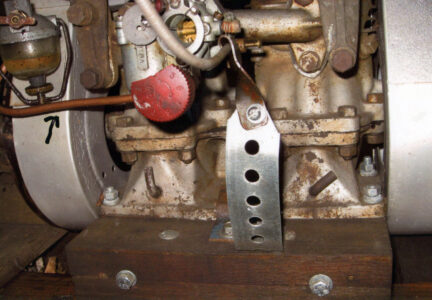
The WICO X magneto was bolted to a cast-iron mount plate that had a section at a right angle to the base. This angled section has a hole in it that acts as a cage for the Lovejoy connection between the mag and engine. The magneto also has an impulse coupler that retards the spark for ease of starting. It is set at top dead center compression for initial timing and advances automatically once the engine gains speed. The cast-iron mount block was slightly bent where the magneto bolted up, making it tilt about 15 degrees from parallel to the engine crankshaft.
As I mentioned before, the wooden base the mag mount was bolted to was intact, but the piece of wood the base was mounted to was broken in half. The lag bolts that mounted the entire assembly had ripped out of the rails of the cart. These bolts were way too short for the job. A run to the hardware store produced the needed piece of wood and longer carriage bolts to mount it to the frame rails, and then the fun began.

I took the assembly apart and decided to test the mag for spark. It was dead. Absolutely nothing from either spark plug wire. I thought that, since the mag was not grounded to the engine, perhaps the coil was bad, but I decided to have a look inside the cover to see what I could see. The four screws came out of the cover easily, and when I turned the mag over, I saw the problem. The points were not opening. I loosened the points’ mount screws and set the points’ running block on the high spot on the cam lobe, and set them at about .018 inch by eye. I tightened the screws.
The magneto has a distributor that directs spark to the plugs. The cap has a spring-loaded contact that touches the coil and leads to a carbon brush that in turn contacts the center of the rotor. The rotor sends the spark out of one of the two terminals to the spark plugs. I reassembled the rotor and cover. The magneto was done.
Mounting the Magneto
The cast-iron magneto mount was bent. The bend would not allow the magneto body to sit straight, so I decided to place a few washers under the base in order to level the mag. It took three or four tries to find the right combination of washer thickness to get it right. The mag bolts were then tightened. The cast-iron mag mount was then mounted onto a 2-inch x 6-inch block. The block had been machined to allow the mag mount to be mounted flat. There were grooves cut into the wood that allowed the mag mount to sit flush.
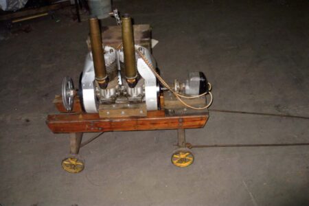
I mounted the rest of the assembly back to the cart. The height was perfect for the vertical alignment with the crankshaft. Getting the side-to-side alignment was not easy. I ended up getting the Lovejoy coupling aligned so the spacing was equal on both sides. The centerline between the mag and the crankshaft were also even. I drew a line around the wooden block onto what I will call the base plate, about 1 inch inside the marked square. I placed the mag mount back on the base plate and used a pencil in the holes, making marks on the bottom of the board. I drilled ¼ x 1 inch deep holes. Four 5/16-inch by 3-inch lag bolts anchored the mount in place.

The only thing left to do was adjust the Lovejoy connection on the crankshaft to allow the magneto to trip at TDC. The Lovejoy assembly consists of a body that is threaded with the keyway inside and the outer diameter of the body is threaded. The front of the Lovejoy, with the alignment pins, is threaded into the body and locked in place by a locknut. The magneto was turned until it tripped and the engine set at TDC compression. A small screwdriver placed through the spark plug hole determined TDC as the engine was rotated. Once the engine was at TDC, I made a mark on the mag side flywheel and the upper shroud to assist in setting the mag at a future date, if necessary, without having to remove the spark plug.
With the engine at TDC and the mag just tripped, it was a matter of aligning the Lovejoy coupling and tightening the lock nut in place. That side of the engine was done. The mag was grounded to the engine by a high-tension support spring from the donor engine.
Starter
Now for the starter. The recoil starter shaft bolts to the flywheel by means of a 3/8-inch bolt. Power to the mower is transferred through this shaft by No. 520 chains and sprockets. The outboard side of the starter has a mount and bushing that supports the outer end of the shaft.

The starter has a pulley about 4 inches in diameter that acts as a spool for the 5/16-inch stainless steel pull-cord. There is a large pot metal pull handle with a spring mounted on it on the end of the pull-cord. A strong spring returns the start cord to a parked position. The recoil spool has a spring-loaded lever on the inside that engages a pawl on the starter shaft. As you pull the handle, the lever engages the pawl, and the engine is turned. When the handle is released, the pulley returns. Unfortunately, the spring on the recoil starter was broken.

I have decided to make a temporary rope starter for the engine. I had a starter cup from an old aluminum block Briggs and Stratton engine that is about 2-1/2 inches in diameter. I found the hole in the nose of the starter side flywheel is almost the same OD size as 1/2-inch iron pipe. I found a ½-inch x 3-inch pipe nipple, and cut the threads off one end. I went back to the hardware store and purchased a 1/2-inch floor plate. The floor plate is a 3-inch disc of steel with a 1/2-inch pipe tapped hole in the center, with four 1/4-inch satellite holes around the perimeter. The holes did not match up with the outside of the starter cup so I drilled my own to mount it to the floor plate. The end of the nipple that had the threads cut off was placed in the flywheel hub mount point and a 3/8-inch drill was placed in the mounting hole. The nipple was drilled into place. The 3/8-inch mounting bolt was installed, and the floor plate was installed on the threaded end of the nipple. The temporary starter was finished.
Fuel System
A quick look at the interior of the fuel tank showed a lot of loose rust. The exterior had been painted, but, after removal and inspection, it showed a real butcher job underneath. There must have been a pound of solder around the two cast-iron mounts for the tank. The side of the tank fared no better and was found to have numerous leaks. The carburetor fuel reservoir vent was plugged by a sheet metal screw, the reservoir itself was full of a strange white rust, and the fuel adjuster needle assembly seems to be bent and frozen in place. The fuel line from the tank into the carburetor was nearly snapped in two at the carburetor and was busted clean off at the fitting on the tank.

The tank fitting is a small assembly, consisting of a housing, a valve, a glass reservoir and a fine screen. There is supposed to be a cork gasket between the bowl and the housing, but it was missing. The tank from the donor engine did not have any holes, but it was loaded with bad gas and gummy residue and had to be cleaned out. I found the carburetor was not working, and the Jacktown show was fast approaching. I decided to mount the fuel tank from the donor engine after I cleaned out the bad gas. The Berkebile carburetor cleaner I used earlier worked great in cleaning out the tank. I installed two Champion No. 9 COM spark plugs, as the plugs in the heads were broken when I bought the engine.
First show
The first show I took the now-nearly completed Twin to was the Blue Mountain Antique Gas & Steam Engine Association Jacktown Grove summer show in Bangor, Pennsylvania. At the show, I started the engine for the first time in over 20 years, and I was surprised at how quiet it was, even with just two vertical pipes for exhaust — no mufflers. I used a squirt-type oil can to feed the intake, and half a pint of gas lasted about three minutes. My chances of finding originals for the twin are practically non-existent.

Carburetor
After the Jacktown show was over, I decided to have a closer look at the pot metal carburetor on the engine. It turns out that this carburetor is not original to the engine. As I said before, the carburetor was full of white rust, and internal passages were blocked. Also the reservoir vent had a screw installed, so the fuel would not enter correctly.
The bore of the engine intake seems to be about 1 inch in diameter. The throat on the carburetor was only about ½ inch. The carburetor was built by Tillotson. I ended up buying another Tillotson carburetor from a vendor at Jacktown, right before I left the show grounds. It has a 1/8-inch pipe inlet for the fuel and a 3/4-inch throat, which I hope will work better on the engine. The new carburetor was mounted on the engine. It needed no alterations to bolt up.
I installed the new 1/8-inch pipe with 1/4-inch compression fittings shrouding shape and size reflected this change. The heads were also turned 90 degrees, allowing the cooling fins to be parallel to the direction of the crank to allow for direct airflow. On my engine, the covers had been lost over time, and I would like to replace them. In the meantime, the heads are mounted in the new configuration, so they can cool with passing air. This is not original for my engine, as it still has the old style tinwork.

The original production run, 1931 to 1941, produced only 807 machines starting with No. 101. I have heard of only three or four complete Twin mowers exist. I know there are several standalone engines as well; if you happen to have one, I would like to know about it.
I have also heard of a second set of Twins made by Jacobsen. I have had contact with two gentlemen who said they had Twins made after production was ended in 1941. One man said he bought his in 1947. The second man I talked to on the SmokStak forum stated he tried to get parts for his in the late 1960s. At that time, Jacobsen told him there were 200 built between 1946 and 1948. Parts were no longer available then.

Jacobson Engine ‘The Twin’ Found at Last Part 1
Restoring ‘The Twin’ Jacobsen Engine Part 2
Contact Andrew Mackey at PO Box 347, Rockaway, NJ 07866 • (862) 432-1552 • mackmotr@aol.com
Attributions
- Harry Matthews and his SmokStak forums on the internet — an invaluable source of information and a lot of good friends!
- Ellis Konkle, who made my wrist pins. Konkle is an excellent machinist. He can be reached at 19 Old Manor Rd., East Port, NY 11941.
- Rockaway Hardware, West Main Street, Rockaway, NJ.
- Shaffer Supply, U.S. Rt. 46, Dover, NJ.
- HM Find, if you have a serial number from a piece of Jacobsen equipment, you can date it and find exactly what the machine is by name. hmfind.com
- Pierre, at the Rockaway Township Library, who put up with my constant questions on how to manage my computer.
- The late Lee Pedersen, a good friend and a great source of engine parts. He was an advertiser at Gas Engine Magazine and a sponsor of the SmokStak forum. He will be missed.
- Austin Wilcox; without him I probably never would have obtained my dream engine!


