


Most engine collectors are familiar with the more well-known
models of Lauson engines such as the spoke flywheel Frost King
series, the disc-flywheel W Series and the various small air-cooled
models built during the 1930s, 1940s and early 1950s. Our purpose
here, however, is to take a look at the now-uncommon Lauson engine
models that were produced between the early 1900s and 1956.
Readers seeking a comprehensive account covering the history and
development of Lauson engines and tractors built prior to 1956
should refer to the November and December 1996 issues of Gas Engine
Magazine. In general, nearly all models of the Lauson horizontal
engines and many of the later ‘high speed’ engines could be
equipped with a gas mixer for running on natural or manufactured
gas instead of gasoline. Engines factory-equipped with gas mixers
are much less common than those equipped with gasoline mixers.
Throttle-governed variations of both the spoke flywheel and W
Series engines seem less common than those equipped as
hit-and-miss.
The Engines
Around 1910, the John Lauson Manufacturing Company introduced a
small horizontal hopper-cooled engine rated at 1 HP at 500-550 rpm.
This engine (Figure 1) was designated the Model Z, and it appears
in Catalog 14 of circa 1910-1911. In magazine ads, the engine was
called ‘The Baby Frost King’.1 Except for the ignition
system, the basic design of this engine was similar to that of the
2-1/2 HP to 5 HP models also shown in Catalog 14. The Baby Frost
King was built with a high-tension, spark plug/buzz coil/battery
ignition system, whereas the standard ignition system on all the
other Lauson models at that time was a low-tension,
igniter/coil/battery system (jump spark ignition was available as
an option on all other sizes of Lauson engines). The Baby Frost
King was equipped with a water-cooled cylinder head, suction-feed
gasoline mixer and hit-and-miss governor. Production of the Baby
Frost King probably ceased sometime around 1913.
Also shown in Catalog 14 is a two-cylinder horizontally opposed
engine (Figure 2) described as being produced in ‘sizes greater
than 25 HP.’ These engines were built only in a plain-cylinder
(not hopper-cooled) design with a flat, double throw crankshaft.
Fuel was gas or gasoline. They featured mechanical operation of the
intake and exhaust valves, throttle-governing and air-to-head
starting. A complete air starting system, including the air
compressor, was furnished with the engine. This model does not
appear in Catalog 18, which is dated 1916.
Sometime around 1913, Lauson introduced two- and four-cylinder
vertical engines with ratings of 18, 25, 36, 50, 80 and 100 HP. By
this time, Lauson was building engines for the DeLaval Dairy Supply
Company, which were sold under the Alpha name. Two- and
four-cylinder versions of these engines are referenced in the
DeLaval-Alpha engines Catalog C 8-13, which is dated 1913.
Four-cylinder versions with ratings of 35, 50 and 60 HP at 450
rpm and 80 and 100 HP at 300 rpm are described in Lauson Catalog 18
of 1916 (Figures 3 and 4). These engines were designed to operate
primarily on kerosene (with gasoline starting), although the
description also references ‘power distillate,’ gas,
gasoline, ‘motor spirits’ and alcohol fuels. The general
construction of these engines featured individual cylinders and
cylinder heads, an enclosed crankcase with five main bearings and
one outboard bearing. Both valves were mechanically operated. The
main bearing and cylinder lubrication was by force feed, with
splash oiling used for the crankpins. A throttling-governor was
used, with a separate carburetor for each cylinder. The ignition
system consisted of a single, low-tension Sumpter magneto and an
igniter at each cylinder. A brass bus bar was used to take voltage
from the magneto to the igniters. Air starting was standard
equipment on the 80 HP and 100 HP versions and included a 1-1/2 HP
engine, air compressor and air tank. The smaller versions used a
‘hand starter,’ but air starting was an option. Production
of these engines probably ceased sometime around 1918.
Also shown in Catalog 18 are 40 and 50 HP single-cylinder
horizontal models rated at 235 rpm (Figure 5). These engines were
described primarily as kerosene engines, but the fuel list also
includes ‘power distillate,’ ‘motor spirits,’ gas
and gasoline. These models were available only in plain-cylinder
versions. A Madison-Kipp force-feed lubricator, feeding the main
bearings, crank pin and cylinder, was standard equipment. The
throttling-governor carburetor was mounted above the cylinder head
and the general construction of these models was in accordance with
the smaller Lauson models. Production of these engines probably
ceased sometime around 1918.
‘Special Electric’ variations of the spoke flywheel
models, designed for driving direct-lighting electric generators,
became available around 1913. Many Lauson Special Electric engines
were sold as the driver on Edison Company electric lighting plants.
These throttle-governed engines were equipped with extra-heavy
flywheels but were otherwise similar to ‘regular’ Lauson
engine models.
Catalog C 8-13 illustrates kerosene burning Special Electric
engines, equipped with the above-head carburetor (Figure 6). This
style of carburetor was used on the Lauson kerosene burning engines
until approximately 1917-1918.
Catalog 18 indicates that the Special Electric engines were
available in plain-cylinder and hopper-cooled styles, in sizes from
2-1/2 to 50 HP. A gasoline-fueled version is shown, with the
suction feed carburetor located beneath the cylinder head. Figure 7
illustrates a gasoline-fueled Special Electric engine equipped with
a Madison-Kipp force-feed lubricator. A 1918 price list indicates
that the Special Electric range covered 3 to 28 HP and that the
engines could also be ordered for burning gaseous fuels. An
instruction book published sometime in the 1919-1924 era indicates
that the Special Electric engines were still available in both the
hopper-cooled and plain-cylinder styles, for gas, gasoline and
kerosene fuels, ranging from 3 to 18 HP (by that time, 18 HP was
the top of the line for the ‘regular’ Lauson engines). The
circa 1924 and 1928 catalogs indicate that the Special Electric
engines were only available as 6, 8, 12, 14 and 18 HP
plain-cylinder models. Production of the Special Electric engines
probably ceased sometime around 1930. These engines are not
described in Catalog A of 1930 (date unconfirmed).
W Series Engines
The W Series disc-flywheel, hopper-cooled models are considered
by many collectors to be ‘common engines,’ but even this
series has some uncommon variations. In the 1924-1925 era, the
3-1/2 HP Model WB was also available in a plain-cylinder variation
(Figure 8). The plain-cylinder WB variation does not appear in
mid-1920s and later catalogs. When the W Series was first
introduced, the standard ignition system was a low-tension rotary
magneto and igniter (although a battery and coil system could be
special-ordered). Starting with serial number 40,000, the standard
ignition system became the Wico EK high-tension magneto with spark
plug. As an option to the EK magneto, a battery/buzz coil
high-tension ignition system was available (Figure 9).
R Series Engines
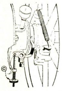
As shown in Catalog A of circa 1930, with production of new air-
and water-cooled ‘high speed’ models well underway, Lauson
was building variations of air-cooled models RA, RAU and RAY
featuring a unique lubrication system that was called a ‘bottle
oiler.’ Figure 10 is a picture of a gas-fueled Model RAG engine
equipped with the bottle oiler.
With this system, an oil supply bottle is located in a housing
attached to the engine base; the bottle was described as being
similar to the kerosene supply bottle used on kerosene-fueled
kitchen stoves. The engine crankcase is isolated from the engine
base by a sheet metal plate having a stamped trough beneath the
connecting rod and an oil pickup tube (with check ball) that
extends into an oil reservoir in the base, downstream of the
bottle. On each upstroke of the piston, crankcase pressure
decreases, allowing oil to move through the pickup tube to fill the
trough. A dipper on the connecting rod then splashes the oil to the
moving parts. Apparently, engines equipped with the bottle oiler
system were not produced for a very long period, because they are
not shown in Catalog B of circa 1933-1934.


