


P.O. Box 518, Painted Post, New York 14870-0518 This is the
second part of a two part series begun in the November 1996
issue.
‘High Speed Beginnings’
Recognizing the beginning of the trend away from the low speed
horizontal cylinder engines, the John Lauson Manufacturing Company
introduced its first vertical cylinder, single cylinder, closed
crankcase, high speed engine models in or around 1929. Air cooled
and water cooled models, based on the same design, were produced.
The air cooled version was designated as the VA, while the water
cooled version was designated as the VR. (Fig. 11)
The flywheel on both of these versions was cast with blower fins
to induce a cooling air draft over the cylinder head and cylinder
or, on the VR engine, through a radiator mounted above the
flywheel.
A variation of the VR, designated as the VW, was equipped with a
plain cooling tank instead of the radiator. The VW was used for
driving milking machines; the hot water from the tank could be used
for washing the milking equipment. Many model VW engines were sold
under the Alpha name.
The VA/VR/VW engines were rated as 1.5 HP at 1200 rpm to 2 HP at
1800 rpm. Both valves are located in the cylinder head and both are
mechanically operated. An enclosed vertical flyball governor was
driven from the end of the camshaft. A Wico B1 high tension magneto
was used. Lubrication was by a combination pump/splash system. A
counterweighted crankshaft with roller type main bearings was used.
Bore and stroke is 2.75′ by 3.25.
A starting crank socket was provided at the flywheel end of the
crankshaft. A laminated paper type of pulley was provided on the
power-take-off (PTO) end of the crankshaft.
From this beginning, the family of Lauson high speed engines
would continue to grow and to change, to meet the demands of
industry.
Catalog ‘A’ of 1930: (date unconfirmed). This seems to
be the first catalog published after the company had become The
Lauson Corporation. In addition to the VA/VR models, this catalog
presents an array of other new models along with the venerable disc
and spoke flywheel models.
A new line of air cooled models was featured, consisting of
models RA, RAU, RAY and LA (Fig. 12).
The basic arrangement of these engines incorporates an L-head,
vertical single cylinder, horizontal crankshaft design having the
valves located perpendicular to the crankshaft. General
specifications are:
RA: HP, 1200-2200 rpm. Washing machine applications.
RAU: 3/4 HP.1200-2200 rpm. General purpose applications.
RAY: 1 HP, 1200-2200 rpm. General purpose applications.
LA: 1.25-1.5 HP,1200-2200 rpm. General purpose applications.
These engines feature a flywheel operated high tension magneto
that resembles the Wico EK magneto. The magneto is arranged with
two sets of stationary magnets, two coils and an H-shaped rotor. A
pin on the flywheel drives the rotor; a cam on the rotor operates
the breaker points. The RA was also available in a battery ignition
version, designated the RAB.
These engines were available in several variations; the base RA
and RAU models used a suction feed gasoline carburetor. The RAY and
LA used a float feed carburetor, and a float feed carburetor was
optional on the RAU. Also optional was an intake air filter. The
suction feed carburetor uses a spool-type throttle valve and is
mounted on the crankcase in line with the governor weights.
The RA, RAU and RAY were available with a unique oiling system
that was called a ‘bottle oiler.’ An oil supply bottle was
located in a housing attached to the engine base; the bottle is
described as being similar to the kerosene supply bottle that was
used on kerosene fueled kitchen stoves. The engine crankcase is
isolated from the engine base by a sheet metal plate having a
stamped trough beneath the connecting rod and an oil pickup tube
(with check ball) which extends into an oil reservoir in the base,
downstream of the bottle. On each upstroke of the piston, crankcase
pressure decreases, allowing oil to move through the pickup tube to
fill the trough. A dipper on the connecting rod then splashes the
oil to the moving parts. These models were also available with a
typical pump/splash lubrication system (which was standard on the
LA).
Timken roller bearing main bearings were used on the LA, while
the smaller models used plain journal bearings. A foot pedal
starter was used on all of these models, although a rope starter
was optional.
A specialized version of the RAU, not shown in the Lauson
catalogs, appears briefly in a DeLaval Milking Outfit ad. This
engine is a water cooled version with a tank cooler similar to the
model VW. Clearly visible is the bottle oiler on the engine base
and the suction feed carburetor on the crankcase.
The VA and VR models discussed previously are illustrated in
catalog ‘A,’ along with new companion models UA and UR. The
air cooled UA and water cooled UR were rated as 2.5-3 HP at
1000-2000 rpm. These engines are based on the VA/VR but use a
larger carburetor and different cylinder head. Variations of this
model series were available using aluminum castings for the base
and ‘other parts.’
The VA/VR and UA/UR models were also available with gear
reduction drives and TWIN DISC over-center clutches.
A new disc flywheel model, the WG, is featured in this catalog.
See Fig. 13. The WG is an enclosed crankcase, hopper cooled engine
rated as 2 HP at 500 rpm to 3 HP at 800 rpm. The bore, stroke and
flywheels are identical to the open crankcase model W.
The WG engine uses Timken tapered roller bearing main bearings
and features splash lubrication of the crankcase components.
Ignition is by Wico EK magneto and spark plug. A water cooled
cylinder head (with atmospheric-operated intake valve) was standard
equipment along with a throttling governor carburetor. A gear
driven flyball governor is located inside of the crankcase. The WG
was available in gas, gasoline and kerosene; semi-portable and
stationary versions.
The W, WA and WB engines are also shown, with the WA being
described as a 2.5-3 HP engine. These engines were still available
in gas, gasoline and kerosene; stationary, semi-portable and
portable versions.
Spoke flywheel hopper cooled models AC (6 HP/450 rpm,), BC (8
HP/375 rpm), DD (12 HP/350 rpm), EE (14 HP/285 rpm) and FG (18
HP/285 rpm) were shown. The models DD, EE and FG continued to use
make and break ignition with rotary magneto. All models were
available in gas, gasoline and kerosene versions, in stationary,
portable or semi-portable types. Stationary engines were available
in plain cylinder versions. Special Electric versions are not
mentioned.
Catalog ‘B’ 1933/1934: (date unconfirmed). Models RA and
RAU are not shown in this catalog. Models RAY and LA carry a
revised speed range of 1600-3500 rpm, with the RAY rated as 1 HP at
1800 rpm and the LA as 1.5 HP at 1800 rpm. The model RAY with
bottle oiler is not shown.
The catalog shows a new water cooled model that was based on the
model LA engine and carried an identical rating. This engine was
designated as the model LWR (Fig. 14). The LWR is equipped with a
radiator; another version of this model, the LW, was targeted at
marine applications.
Another new model, the UAS (Fig. 15), replaced the earlier VA
and UA models. The UAS was rated as 3 HP at 1800 rpm and would
develop 4.3 HP at 2500 rpm. This engine evolved from the VA/UA
models but uses a different governor, carburetor and cooling shroud
arrangement. A Wico LD high tension magneto was used on the UAS.
The model VR was retained and was also rated as 3 HP at 1800 rpm
and 4.3 HP at 2500 rpm.
Catalog B also features the model UW water cooled engine. This
engine had an 1/8‘ larger cylinder bore
than the VR and UAS models and was rated as 4 HP at 2000 rpm. The
general construction of this engine was similar to the UAS engine.
Marine and radiator cooled (UWR) versions were available.
The LA, UAS, VR, LWR and UWR engines were also available with
gear reduction drives and TWIN DISC clutches.
An air cleaner was an option for all of the high speed models.
This catalog illustrates models W, WA, WB, WG, AC, BC, DD, EE, and
FG with no change in description from catalog ‘A.’
Also shown is a V-belt type of centrifugal clutch pulley,
designed by The Lauson Corporation, that was available for engine
applications to 4 HP. This pulley continued to be produced for
several years and is also shown in subsequent catalogs.
Catalog ‘D’ dated 12-16-35: This appears to be the first
catalog released after the company had become The Lauson
Company.
A new fractional horsepower engine was introduced in this
catalog, the model RL. This new model was much smaller than the RA
and RAU models that had been produced in the early 1930s. The RL
was rated as HP at 1800 rpm to 3/4 HP at 3600 rpm and weighed less
than 30 pounds.
RL features include a mechanical governor located inside of the
crankcase, suction feed carburetor, ball bearing main bearings,
splash lubrication and a ‘modern’ type of flywheel magneto
having the magnets carried in the flywheel. The valves are located
perpendicular to the crankshaft. The standard version was
designated as the RLA; another version, having a vertical
power-take-off attachment for use on washing machines, was
designated as the RLB.
The model RAY is shown, while the LA has been replaced by the
model LB. The LB was rated as 2 HP at 1800 rpm to 2.5 HP at 3000
rpm. The model UAS is shown at the same rating as shown in catalog
‘B.’ The earlier model LW engine had been replaced by the
LF (which has a slightly larger cylinder bore); the LF was rated as
2.25 HP at 1600 rpm to 2.75 HP at 2000 rpm. The radiator equipped
version of the LF was designated as the LFR.
The UW engine retained its rating of 3.5 HP at 1600 rpm to 4.5
HP at 2500 rpm. The UWR radiator equipped version was available.
Model VR is not shown in this catalog.
This catalog also shows another new water cooled model, the ZW.
The general construction of the ZW was like that of the UW, but
with a slightly larger cylinder bore. The ZW was rated as 4.75 HP
at 1600 rpm to 5.6 HP at 2000 rpm.
The catalog indicates that air cleaners, radio shielded ignition
systems and gaseous fuel carburetors were available for all
vertical cylinder models.
As shown in Catalog ‘D,’ models W and WG remained
unchanged but the WA was now rated as 2.5 HP at 500 rpm to 3.5 HP
at 600 rpm, and the WB was rated as 3.5 HP at 400 rpm to 6 HP at
625 rpm. Gas, gasoline and kerosene versions remained available in
the stationary, semi-portable and (except WG) portable types.
The catalog also shows that some of the spoke flywheel models
had been rerated. The AC was rated as 6 HP at 450 rpm to 8 HP at
600 rpm, and the BC was rated as 8 HP at 375 rpm to 10 HP at 525
rpm. The ratings on models DD, EE and FG remained unchanged. These
models continued to be offered in gas, gasoline and kerosene
versions but only in stationary and semi-portable types. Plain
cylinder stationary types were available. This catalog also
indicates that the spoke flywheel models could still be ordered
with a force feed lubricator.
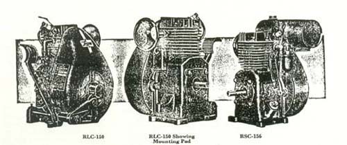
Catalog ‘F’ dated 9-15-37: This catalog shows that the
original RL model was now designated as the model RLC. The RLC was
rated as HP at 1800 rpm to 3/4 HP at 3000
rpm. A new companion model, the RSC, is also shown. The RSC was
rated as 3/4 HP at 1800 rpm to 1 HP at 3000
rpm.
The RLC and RSC (Fig. 16) engines embodied the same general
features such as ball bearing main bearings, mechanical governor
located inside of the crankcase, and splash type lubrication. The
intake and exhaust valves were located perpendicular to the
crankshaft.
These models were available in several variations offering a
choice of battery or flywheel magneto ignition, float feed or
suction feed carburetor, and foot pedal, rope or hand lever
starters.
The RLC used a four-bolt cylinder head while the RSC, with its
slightly larger cylinder bore, used a six-bolt cylinder head.
Models RAY and LB are shown, at the same ratings shown in
catalog ‘D.’ These engines were available with foot pedal,
hand crank or rope starters. Gear reduction and clutch options are
listed for the model LB.
Models LFR, UAS and ZWR are also shown, at the same ratings as
indicated in catalog ‘D.’ Model UW is not shown.
Air cleaners, radio shielding and the substitution of aluminum
castings (on the heavier models) continued to be options on the
vertical cylinder models.
The end of the production of the hopper cooled, double flywheel
models was drawing near. This catalog lists only models W, WA, WB
and AC in the same ratings as described in catalog ‘D.’
These engines were available in gasoline or kerosene versions,
stationary or semi-portable.
1940-1942
This period saw the end of an era, with production of the double
flywheel models ceasing around 1940. Production of models UAS and
ZWR also ended around 1940. The ZW, in a marine version, continued
to be produced into the early 1940s. By July 1940, the model RC was
in production. The RC is a 1.5 HP water cooled engine based on the
RSC. A radiator equipped version, the RCR, was also available. The
2.25 HP model TLC had also been introduced by 1940.
1941 Price List: Dated August 5, 1941; lists the following
models: Air Cooled
RLC1/2–3/4 HP (suction
feed or float feed carburetor).
RSC 3/4-l HP (with suction feed
carburetor).
RSC 1.5 HP (with float feed carburetor).
TLC 2.3 HP.
RAY 1.75 HP.
LB 3 HP.
Water Cooled
RC 1.5 HP.
LF3.7HP.
The list indicates that various types of air cleaners were now
standard equipment on all models.
The RLC and RSC models were available with either magneto or
battery ignition, with a choice of foot pedal, rope or hand lever
starter, and a gear reduction drive. A lighting coil could be added
to the magneto.
The TLC engines were available with a choice of hand crank or
rope starter, gasoline filter, gear reduction drive, magneto
lighting coil and no air cleaner.
The RAY engines were available with a choice of foot pedal, hand
crank or rope starter. The LB engines were available with a choice
of foot pedal, hand crank or rope starter, gear reduction drives
and TWIN DISC clutch.
Options for the models RC and LF are not described.
1940 Marine Models
Catalog 0-97A, dated 12-15-39, describes the following marine
models which are variations of standard industrial models:
RSM 1.5 HP air cooled.
RCM 1.5 HP water cooled.
TLM 2.25 HP air cooled.
RLM 0.75 HP air cooled.
LBM 3 HP air cooled.
LF 3.7 HP water cooled.
ZW 5.5 HP water cooled.
All of these model versions, except the ZW, were supplied less
governor, with a hand throttle control connected directly to the
carburetor. A water pump was included as standard equipment on the
water cooled models.
Other standard features included a marine style engine base,
flame arrester air cleaner, magneto ignition and, except for the
RLM, a float feed carburetor. The RLM was equipped with a suction
feed carburetor.
Various combinations of reversing gear drives and gear reduction
drives were options for all of these engines. A reverse gear was
included as standard equipment on the TLM and a reduction-type
forward/reverse V-belt drive was standard equipment on the RLM.
The RLM, RSM, RCM and TLM engines could be furnished with a
lighting coil in the magneto, while the LF could be ordered with a
ring-gear type of electric starter and V-belt driven generator.
This catalog also lists a number of accessories such as
propeller shafts, shaft couplings, shaft bearings, rudder skegs,
rudders and marine mufflers.
The Hart-Carter Years
Following the June 1941 purchase of The Lauson Company, the
Hart-Carter Company allowed the Lauson plant to continue to operate
without change of policy or personnel. The plant became known as
The Lauson Company, a division of Hart-Carter Company.
Through its affiliation with Hart-Carter, Lauson was able to
step up its production tempo and also improve manufacturing
methods. During World War II, Lauson went into production of
lightweight aluminum engines to minimize the weights that military
forces had to handle while carrying Lauson-powered equipment to
battlefronts all over the world.
To improve the durability of engines operating on 100-octane
leaded gasoline, Lauson began production of engines equipped with
Stellite faced valves and valve seats. In 1942 the company set up
its own Stellite facing department.
Lauson quality earned the company the Army-Air Force’s
‘A-Rating,’ which was given only to those companies whose
methods of inspecting and testing eliminated the need for
additional Army checking.
1946 Catalog: (date unconfirmed). In what appears to be the
company’s first post-war catalog, the Lauson Company and Lauson
engines are reintro-duced to the reader. The catalog offers a list
of Lauson ‘firsts’ that had originated during the
company’s first 50 years of engine production. Some of these
are quoted below:
‘Lauson was the first to use hopper cooling for gasoline
engines.’
‘Lauson was the first to mix water and fuel in kerosene
burning engines and holds the original patent on this
feature.’
‘Lauson was the first to build light-weight, air cooled
industrial engines with ball bearings on each end of the
crankshaft.’
‘Lauson was the first to design and build the TACO governor,
used for many years on Fordson tractors and industrial
engines.’
(I have tried neither to prove, nor disprove, the validity of
any of these claims.)
The 1946 catalog features the following models:
RLC: 0.65 HP at 1800 rpm to 0.98 HP at 3600 rpm.
RSC: 0.82 HP at 1800 rpm to 1.5 HP at 3600 rpm.
TLC: 1.42 HP at 1800 rpm to 2.32 HP at 3600 rpm.
PAC: 3.28 HP at 1800 rpm to 4.20 HP at 3000 rpm.
RC: 1.09 HP at 1800 rpm to 1.65 HP at 3600 rpm.
LF: 2.2 HP at 1800 rpm to 3.7 HP at 3600 rpm.
Rope starters, oil bath air filters and moisture proof magnetos
were standard equipment on all of the base models. A ‘scooter
engine’ variation of the model TLC is shown with a foot pedal
starter and ‘pancake’ air filter. The air cooled models
were equipped with a sediment bowl type of fuel strainer. Water
cooled models were equipped with a water circulating pump.
Other options for the various models included: stub shaft PTO on
flywheel side of engine, deep-sump base, low oil level shut down
switch, rain-proof features, spill-proof features (to prevent oil
and fuel spillage during transport), high-octane fuel
‘package,’ gear reduction drives and radio shielding.
Two-spark magnetos were also available. During World War II,
many Lauson engines were applied as the driver on gasoline-fired
aircraft heating units. The engine magneto also furnished voltage
to a spark plug in the burner of the heater.
Late 1940s/Early 1950s
Around 1947 the model RSV began to be built. This was a vertical
crankshaft engine that had been developed in cooperation with Mr.
Leonard Goodall of the Goodall Manufacturing Company. The engine
evolved from the RSC horizontal crankshaft model and utilized a
special oil pump and lubrication system that enabled the engine to
be mounted with the crankshaft vertical. In 1948 Mr. Harold Bruns
(president of Lauson) agreed to sell these engines exclusively to
the Goodall Manufacturing Company for a period of two years,
therefore, all of these first vertical crankshaft engines were
applied on Goodall rotary mowers.
By 1948, the model PMM water cooled inboard marine engine was in
production. The PMM was rated as 5.5 HP at 3000 rpm. This engine
was furnished without a governor. Ignition was by flywheel magneto.
Two versions were available, one having a plain rope starter and
the other featuring a ring gear type of electric starter and
belt-driven generator.
Also by 1948, the model LMC was in production. This little
engine produced 3/4 HP at 3500 rpm. A rope
starter, flywheel magneto, float feed carburetor and fiber-type air
filter were standard equipment.
By early 1951 models RLC, RSC, LMC, TLC and PAC were obsoleted
by models RSH, LMH, TLH and PAH, which have higher horsepower
ratings than the previous models. Verbiage on several individual
model specification sheets dated 1951 indicates that water cooled
marine models were no longer produced.
By 1951, model 55S, 1.5 HP, and 55AB, 2 HP, were in production.
These engines resemble the model RSH but were constructed with
sleeve bushing main bearings. The 55S was supplied with a suction
feed carburetor, while the 55 AB was supplied with a float feed
carburetor.
By July 1954, the model SLV (‘Super Light Vertical’) was
in production. The SLV (Fig. 17) rated 2 HP at 3600 rpm, is an
aluminum crankcase, vertical crankshaft engine designed
specifically for lawn mower applications. The SLV is of L-head
design with a full pressure lubrication system serving the camshaft
and crankshaft. The plunger type oil pump is driven by an eccentric
on the camshaft.
The SLV was the first Lauson engine to use a pneumatic governor.
The air blast from the flywheel cooling fan impinges on a swinging
air vane located beneath the cooling shroud. The air vane is linked
to the carburetor throttle; a speed setting spring acts to open the
throttle. With the engine running, air pressure acting on the air
vane overcomes the spring force to close the throttle. Under load,
as the engine speed drops, spring force becomes greater than air
vane force, which allows the throttle to open slightly to restore
engine speed to the setpoint.
The original SLV used a rope starter. Ignition was by a flywheel
magneto. A float feed carburetor was used. The gasoline tank was
incorporated into the cooling shroud. Oil bath or mesh-type air
cleaners were available.
By March 1956, a 2.5 HP companion model, the VA, was in
production.
1955 Service Manual, dated May 1955, shows the following array
of engines:
Horiz Crankshaf | Vert Crank | ||
LMH | 1 HP | LMV | 1 HP |
RSH | 2 HP | RSV | 2 HP |
TLH | 3 HP | TLV | 3 HP |
PAH | 5.5 HP | R | 2 HP |
PAX | 5.5 HP | V | 2 HP |
P-25 | 6.25 HP | SLV | 2 HP |
55-S | 1.5(?)HP | ||
55A | 2 HP | ||
55AB | 2 HP | ||
All of the vertical crankshaft models except the SLV were
adaptations of the horizontal crankshaft models. The model R
included an auxiliary horizontal PTO shaft.
Models 55A and 55AB featured a different mounting pad on the PTO
side of the crankcase. Models PAX and P-25 featured a gear driven
high tension rotary magneto; all other models used a flywheel
magneto.
Oil Test Engine
The model H-2 oil test engine was another specialized Lauson
model. The H-2 is a water cooled model rated as 4.3 HP at 2400 rpm.
The outward appearance of this engine is similar to the earlier
model PMM. The H-2 was built specifically for use by oil companies
in the testing of lubricating oils. Prior to the introduction of
the H-2, many oil companies were using models RC and LF for oil
test work.
The H-2 was supplied with a rope starter, mechanical governor,
flywheel magneto, float feed carburetor, pump/splash lubrication
and ball bearing main bearings.
Standard special features of the model H-2 included an electric
heater built into the engine base, a removable dry-type cylinder
sleeve, evaporative cooling system with condensing tank on cylinder
head, hinge between cylinder block and engine base to facilitate
inspection or overhaul, covered hand hole in side of engine to
facilitate inspection of connecting rod and bearing shell, Stellite
facing on exhaust valve and seat, and adjustable spark timing.
Optional equipment consisted of an oil bath air cleaner and
standardized loading fan with guard.
The H-2 had been introduced in the mid-1940s and continued to be
produced through 1957.
Outboard Boat Engines
In 1940 the Lauson Company introduced the first of a series of
four-cycle, air cooled outboard ‘motors.’
The ‘Sport King’ four-cycle design, without the need to
mix fuel and oil, became a major selling point and allowed the
engines to idle smoothly during trolling.
The 2.5 HP model A-410 (Fig. 18) was produced from 1940 through
1947, with production being suspended during World War II. The
A-410 is a single cylinder model featuring a float feed carburetor,
flywheel magneto, ball bearing main bearings and a pressurized
crankcase lubrication system. The engine does not have a
governor.
In 1948 two new outboard models were introduced (Fig. 19); the 3
HP, single cylinder S-300 and the 6 HP twin cylinder T-600. The
general construction of these models is similar to the A-410. These
models were built through 1949. They were followed by the S-350 and
T-650 in 1950, the S-351 and T-651 in 1951 to 1952, and the 5-353
and T-653 from 1953 to 1955. The T-651 and T-653 were available
with a reversing gear, denoted by an ‘R’ suffix on the
model number.
A1955 service manual indicates that the Lauson outboard motors
were manufactured at a plant in Vandalia, Illinois.
The Tecumseh Years
In January 1956 the company began operating as the Lauson
Division of Tecumseh Products Company. Production of the Sport King
outboard motors ceased, in accordance with Tecumseh policy that no
end products would be manufactured that would place Tecumseh in
competition with its customers.
By the late 1950s, the Lauson line consisted of the following
models:
Aluminum Frame, Vertical Crankshaft: V-17 1.75 HP, V-20 2 HP,
V-22 2.25 HP, and V-25 2.5 HP.
Cast Iron Frame, Horizontal Crankshaft: CH-17 1.75 HP, CH-20 2
HP, RSH-737 2 HP, TLH-725 3.3 HP, and P-25 6.3 HP.
By the 1960s, the Lauson Division was producing aluminum frame
horizontal crankshaft models whose descendants still appear in the
present Tecumseh engine line.
By the early 1970s, the Lauson Division was again building
overhead valve models: the cast iron frame, horizontal crankshaft
HH-140 of 14 HP and the HH-160 of l6 HP.
By 1988 overhead valve construction was featured on two of the
aluminum frame, vertical crankshaft models: the OVRM40 of 4 HP and
the OVXL120 of l2 HP.
Today, the Tecumseh line offers a wide array of engines. Several
overhead valve models are available in addition to the typical
L-head models. An oil filter is an option on certain vertical
crankshaft models. The four-cycle, vertical crankshaft engines
range from 3.5 to 16 HP, while the four-cycle horizontal crankshaft
engines range from 3 to 18 HP.
Lauson Tractors
In 1915 The John Lauson Manufacturing Company began production
of a line of farm tractors. These tractors came to be called the
‘Full Jewel’ tractors because the design featured extensive
use of ball and roller bearings.
The April 1916 issue of ‘The Lauson Power Magazine’
focuses on the new tractor, which was being produced in two models
(Fig. 20). This publication contains a picture of an earlier,
experimental Lauson tractor having a rounded stack draft-type
radiator and vertical cylinder in-line type of engine set
perpendicular to the tractor frame.
The 1916 and later Lauson tractors were built with the engine
mounted parallel to the tractor frame and a conventional fan-cooled
type of radiator. The two models were rated as 15-25 HP and 20-35
HP. Both models feature a four cylinder overhead valve engine (not
built by Lauson) with a Dixie high tension magneto. An over-center,
hand lever operated clutch was used.
The transmission/belt pulley drive was fully enclosed, but the
final drive gears at the rear wheels were open. Travel speeds were
2.5 mph and 1.75 mph. These first models were built with a
‘squared-off’ cab and no rear fenders. Sheet metal side
panels enclose the engine, fuel tank and transmission.
Tractor Bulletin 250: dated 8-23-17. describes only the model
15-25 tractor. The cab had been deleted and rear fenders added. The
rear fenders sweep down behind the wheels, to the level of the
operator platform (Fig. 21). The four cylinder, overhead valve ERD
engine is shown equipped with a belt-driven mechanical governor.
The engine cylinder block was cast separately from the crankcase.
Kingston carburetor and Dixie magneto are used. The final drive
gears at the rear wheels are open.
A 1918 booklet describing the 15-25 tractor shows several
changes. The final drive gears at the rear wheels are enclosed and
the housings provide oil bath lubrication of the gears. A four
cylinder, overhead valve BEAVER engine had been adopted. The Beaver
engine is equipped with a gear driven mechanical governor (located
at the flywheel end of the engine) and a Dixie high tension
magneto.
By 1920, the model 15-25 tractor had been uprated to 15-30 HP.
This model continued to use a Beaver engine. The 15-30 was
available as a standard farm tractor and in a ‘road
tractor’ version with extra-heavy rear wheels.
Around 1920, the model 12-25 (12-25 HP) was introduced. This
model used a four cylinder MIDWEST engine. This model also had the
engine, fuel tank and transmission enclosed by sheet metal side
covers.
By 1927 models 16-32 (16-32 HP) and 20-40 (20-40 HP) were in
production. These models feature four cylinder, overhead valve
Beaver engines having the cylinder blocks cast in pairs separate
from the crankcase. The engine used in the 16-32 features a bore
and stroke of 4.5′ by 6′. The engine used in the 20-40
features a bore and stroke of 4.75’by 6′.
The year 1928 brought the introduction of the model 20-35, also
designated as the S12 (Fig. 22). This is a four cylinder model with
a rating of 20-35 HP. The S12 uses a LeRoi/Beaver engine of
4-5′ by 6′ bore and stroke. This engine appears to be
identical to the Beaver engine used in the model 16-32.
A six cylinder model, the 25-45 (25-45 HP) was also new for
1928. This model also uses an overhead valve LeRoi/Beaver engine
with the same bore and stroke as used on the four cylinder 20-35
model.
The appearance of models 16-32,20-40, 20-35 and 25-45 differs
slightly from that of the earlier models because sheet metal side
covers are not used. The design of the operator’s platform and
rear fenders is similar to earlier models. The engines of these
models use a gear driven TACO governor, located at the flywheel end
of the engine. The nameplate on these governors indicates that they
were built by the Tractor Appliance Company, of New Holstein,
Wisconsin. A TACO water-bath air filter is used on these models.
Ignition is by an American Bosch magneto.
Many of the 20-35, 20-40 and 25-45 tractors were sold by the
Nichols and Shepard Company, with a Nichols and Shepard
nameplate.
Near the end of production of the Lauson tractors another six
cylinder model, the 6-S, was produced. This model used a Wisconsin
engine and carried a 22-36 HP rating.
New production of Lauson tractors ended around 1932 when severe
crop failures in the Midwestern states caused many farmers to
default on their payments. Following the end of production a
quantity of between 12 and 15 tractors was built using parts from
inventory. I have been told that these tractors were rated as 12-24
HP and used a four cylinder Wisconsin engine. A single employee
assembled this last batch of tractors. By 1935, a number of Lauson
tractors that had been repossessed were brought back to the
factory, refurbished and resold.
Acknowledgments
In closing this article, I would like to express a sincere
‘thank you’ to all who have helped me, over the years, by
providing Lauson information.
I would especially like to thank Ron Steiner, of Tecumseh
Products Company, and Harold Bruns, president of Lauson from 1947
to 1956, for their assistance and patience during my most-recent
research.
I plan to use the information presented herein as the basis for
a pictorial essay book about Lauson Engines and Tractors. I will
welcome input from anyone having information beyond what I have
compiled, especially date-specific information.


