


The following is the third in a series of articles from the 1923
edition of Modern Mechanical Engineering, on the subject of gas
engines. The original articles were sent to us by Jan vander
Gugten, 2633 Ware Street, Abbotsford, B.C., Canada V2S 3E2, who
thought our’ readers would find them of interest. The first two
installments appeared in our April and May 1997 issues.
CHAPTER IV: GOVERNING
Engines in general are required to maintain a considerable
degree of uniformity in their speed under normal working
conditions, and in this respect the single-cylindered single-acting
four-stroke engine is at a serious disadvantage, as a working
impulse occurs only, at best, once in every four strokes; the
momentum of massive flywheels thus has to maintain rotation during
at least three-fourths of the running time. This inherent drawback
is, however, reduced to a practically negligible amount: (a) by
using multi-cylindered single-acting engines; (b) by using tandem
or twin-tandem double-acting engines; and (c) by using two-stroke
single-or double-acting engines; and in nearly all cases with the
addition of a massive flywheel.
Speed Fluctuation. The coefficient of
fluctuation of speed of an engine is defined as the ratio of the
difference between the maximum and minimum angular velocity of the
crank-shaft per cycle to its mean angular velocity. The permissible
value of this coefficient depends upon the nature of the work
performed by the engine; usual values in a number of typical cases
are given here-under:
Approximate Permissible | |
Nature of Service | Coefficient of Speed Fluctuation. |
Driving pumps | 1/20 |
Driving machine tools | 1/35 |
Driving textile machinery | 1/50 |
Driving C.C. dynamos | 1/200 |
Driving spinning machinery | 1/100 |
Driving direct-coupled alternators in parallel | 1/250 |
Cf. R. E. Mathot, Construction and Working of I.C. Engines
(Constable), or Clerk and Burls, The Gas, Petrol, and Oil Engine,
Vol. II (Longmans).
For a full account see Clerk and Burls, Vol. II, Chapter IV.
So long as the external resistances overcome by the engine
remain unchanged, cyclic speed fluctuation can be reduced to any
desired extent by providing sufficient flywheel inertia; for a
detailed consideration of this question reference must be made to
the larger special treatises.
When the external resistance is changeable, it is usually
necessary to provide that the engine speed shall not be permitted
to vary from the normal by more than a small amount, and some
system of governing thus becomes essential.
The governor itself is almost always of the centrifugal type of
which the well-known ‘conical pendulum’ of Watt is the
parent; such governors have been greatly developed in recent years
by ‘British and German engineers, among whom may be mentioned
Hartnell, Prll, Beyer, Hartung, and Rost.
In all these centrifugal action, due to varying engine speed,
provides motion which is applied to vary the quantity or quality of
the explosive charge admitted to the engine cylinder in one or more
of the following three principal ways:
1. By completely cutting off the gas supply in one or more
cycles ‘hit-or-miss’ governing.
2. By partially cutting off the gas supply, thus varying the
quality of the mixture, the mass of the charge remaining
unchanged.
3. By varying the opening of the mixture valve, thus varying the
quantity of charge admitted to the cylinder, keeping the ratio of
gas to air unchanged.
‘Hit-or-miss’ Governing. In this method when engine
speed increases one or more charges of gas are completely cut out,
so that no working stroke occurs until the speed falls again to
about its normal value. It was for long almost universally employed
in stationary gas-engines, and is still widely used in engines of
up to about 100 b.h.p. (as, e.g., by the Campbell Company) in cases
where extreme uniformity of speed is unnecessary. It possesses the
advantage of giving economical fuel consumption both at light and
at full loads, and is mechanically simple and reliable.
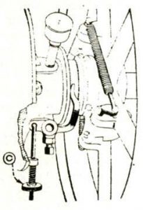
A simple and effective hit-or-miss arrangement is illustrated in
Fig. 7. The ‘pecker’ P normally opens the gas valve H
through the ‘pecker block’ D, suspended by a rod C from a
lever A which is pivoted at B; obviously a very small rise of the
governor balls suffices to lift D out of the way of the pecker P,
and when this occurs the gas valve remains closed. The governor is
easily and quickly adjusted by varying the spring compression by
aid of the milled nuts N on the top of the governor spindle.
Quality Governing With this method of
governing, the mixture becomes progressively weaker as the load on
the engine diminishes, though the compression pressure is constant
since the mass of the charge remains unchanged. The reduction in
the gas admitted is usually affected either: (1) by shortening the
duration of opening of the gas valve, the air admission remaining
constant; or (2) by throttling the gas supply throughout the
suction stroke, with constant air admission. Often the gas valve is
not opened until part of the suction stroke has been performed,
thus providing a rich and readily ignitable mixture near the firing
plugs in the combustion chamber.
At light loads the weak mixtures supplied to the engine were at
first difficult to ignite and burned slowly; heat losses were thus
often much increased, and the charge was also often not fully
burned before release occurred. Combustion was occasionally so slow
as to persist during the exhaust stroke and explode the succeeding
fresh charge, thus causing what is termed as ‘back fire’.
Both these drawbacks are practically overcome by delaying the
opening of the gas valve until part of the suction stroke has been
performed.
By simply stepping the pecker block as shown in the lower
portion of Fig. 7, a crude form of quality governing is readily
obtained. With a stepped pecker block the pecker, when raised by
the action of the governor, moves the gas valve not only later but
also through a smaller lift, and finally, when the speed-change is
considerable, misses it altogether.
The Premier gas-engines are governed on the ‘quality’
method; a centrifugal spring-loaded enclosed governor driven from
the crankshaft by skew gearing controls a throttle valve in the gas
supply. A difficulty gas-engine designers have to overcome is that
of the considerable variation in the quantity and composition of
the gas supplied to the engine, particularly when only one suction
producer is employed, and pro -vision for manual adjustment of the
mixture is therefore necessary. In the Premier engines a
hand-adjusted master-throttle determines the total air supply to
the engine, while separate throttles to the cylinder enable the
mixture strength of each to be independently regulated.
Quantity Governing. In this method, the mass or
‘quantity’ of the working charge is reduced as the engine
load diminishes, but the ratio of air to gas is kept unaltered; the
compression pressure is accordingly also then reduced. Sir Dugald
Clerk observes:
‘The reduction in the compression pressure causes some
diminution of thermal efficiency at such times; but as the
compression and expansion curves rise and fall together the
variation of crank-pin effort is not unfavourably affected. With
poor gas of small hydrogen’ content high compression pressures
(175 lb. per square inch and above) may safely be used, thus giving
increased economy and more rapid and complete combustion of the
charge, and in such cases quantity governing is most satisfactory,
since the compression at light loads remains still high enough to
ensure ready ignition of the mixture…the frictional resistances
of the engine are also reduced by the diminished compression. On
the whole the balance of practical advantage in general favors
governing by this method rather than by that of quality.’
Quantity governing is largely employed, as, e.g., in the
Browett-Lindley, Crossley, Hornsby-Stockport, and Tangye
gas-engines. The exceedingly simple and effective ‘shifting
fulcrum’ device used in the quantity governing of the Crossley
gas-engines is shown in Fig. 8, wherein the rocking lever fulcrum
is in the position for light load; at full load the governor moves
the fulcrum towards the right, causing the two arms of the rocker
to become nearly equal, thereby increasing the lift of the mixture
inlet valve. The gear being in full view of the attendant,
inspection of the position of the fulcrum indicates at once the
amount of load on the engine. With this governor the permanent
speed variation between no load and full load is only about
2percent from the mean. Messrs. Tangye also use a shifting fulcrum
device, but of somewhat different type.
The governing arrangement used in the ‘National’
gas-engines ingeniously combines all three methods, viz. of
hit-or-miss, quality, and quantity; it is illustrated
diagrammatically in Fig. 9. The gaseous mixture is admitted to the
combustion chamber of the cylinder through the charge inlet valve
A; this valve is operated by its cam in an unvarying manner at all
loads, opening about 15° before inner dead centre, and closing
about 55° after outer dead centre of the crank-pin. The air valve B
is a circular disc’ of somewhat smaller diameter than the hole
in the casing in which it works, so that even when the gas-valve C
remains seated it is still possible for air alone to enter the
cylinder through the charging valve A.
The cam D on the side shaft actuates the air-valve spindle and
through this the gas valve also as indicated through the agency of
the two levers E and F and the governor-controlled plate H, the
lever E is pivoted at K, and when the cam D is out of action the
serrated ridge of the lever E is clear of the plate H, and during
such times the governor is free to raise or lower this plate
agreeably with its speed of rotation. When the speed increases, H
is raised and the opening of the gas and air valves is then
reduced, and vice versa; in this way the lift of these valves may
be varied from ? inch at light loads to inch at full load.
The cam D is so shaped that the cutoff point of the gas remains
nearly constant; the gas is cut off early enough to allow the
combustible mixture in the space below the charging valve to be
sucked into the combustion chamber before this valve closes. This
is necessary in order that this space may be filled with air which
then alone enters the cylinder at the commencement of the next
suction stroke, thus cooling the residual exhaust gases before
fresh inflammable mixture enters the combustion chamber.
At full load the plate H occupies its lowest position, and a
full charge of gas and air is admitted. For somewhat smaller loads
the gas supply is reduced while the air supply suffers but little
diminution; the mass of the charge and accordingly the compression
pressure are therefore but little affected, and the governing is of
the quality type. At lighter loads the air valve B is nearer to its
housing, and the ratio of gas to air admitted then remains more
nearly constant while the mass admitted is reduced; the governing
is then of the quantity type. Finally, at very light loads the
plate H may be raised so high that it is occasionally missed
altogether by the serrated ridge of the lever E, and the governing
is then of the hit-or-miss type.
CHAPTER V: Starting
For gas-engines of less than about 30 b.h.p. no special starting
apparatus is usually needed. When preparing to start, attention
should be given: (1) To the oiling system. All lubricators and oil
reservoirs should be replenished, oil wicks adjusted, and
sight-feed lubricators started. (2) To the cooling water system.
The cock on the water-supply-pipe to engine should be opened, drain
cocks closed, etc. (3) The inlet, exhaust, and throttle valves
should be moved by hand to ascertain that they are not ‘gummed
up.’ (4) The driving belt should be on the loose pulley. (5) If
a compression relief be fitted, the exhaust valve roller should be
placed opposite the narrow or ‘relief cam. (6) The ignition
should be fully retarded. (7) The gas should be turned on only when
ready to start, ascertaining first that the gas-supply pipe is free
from air and charged with pure gas up to the engine by turning on
the vent pipe and lighting the test burner until it burns well and
steadily. (8) The flywheel should next be turned by hand as quickly
as possible until the engine starts, pulling downwards on the rim
and away from the engine; the feet should never be placed on the
flywheel spokes. (9) After a few explosions have occurred the
ignition may be slightly advanced and the relief cam put out of
action. (10) When full speed is attained and the engine is warmed
up the ignition should be advanced to the normal working position,
and the air and gas regulators adjusted. Finally the load may be
imposed on the engine.
With engines of over about 30 b.h.p. some form of special
starting apparatus is, in general, necessary. Flywheels arc usually
furnished with a series of holes round the rim for the insertion of
a crowbar, or an internally-toothed ring operated by a small pinion
and hand-wheel or small motor, by which the engine may be
‘barred’ round so as to place the crank-pin in a favorable
position for starting, i.e. 15° to 20° beyond the inner dead centre
on the firing stroke.
Many medium large gas-engines, from 30 or 40 b.h.p. up to about
200 b.h.p. are started by means of a small pump fitted to the
engine, by which an initial charge of gas and air is pumped by hand
into the combustion chamber and ignited by ‘flicking over’
the magneto by hand. The explosion thus obtained imparts sufficient
motion to the engine to enable it to take up its normal working
cycle. A small quantity of petrol is often pumped in with the air,
as an alternative to gas, and this gives a more powerful starting
impulse. Such starters are very effective, and are used, e.g., in
the National’, Anderson-Grice, and Brotherhood gas-engines.
With large gas-engines the single impulse furnished by the
hand-pump method is insufficient to effect a start, and accordingly
compressed air, stored in cylindrical steel reservoirs, is employed
for starting purposes. With new engines the reservoir is sent out
charged, hut thereafter its pressure may be maintained: (1) from
the engine cylinder and piston through a special delivery valve; or
(2) from a small air-compressor belt-driven by the engine; or (3)
by a small auxiliary engine and air-compressing pump. Starting by
compressed air is very simple; a cam opening a small compressed-air
supply valve in the combustion chamber, during the earlier part of
the firing stroke, is put in action. The compression relief cam of
the engine is also put in action and the ignition retarded; the
engine is then barred round until the crank-pin is in the starting
position (i.e. just well over the inner dead centre on the firing
stroke); and the gas is turned on. On opening the air reservoir
cock the engine at once commences to turn, and usually takes up its
normal working cycle after three or four air impulses. The
air-valve cam is then moved out of action and the air cock shut;
the reservoir is made of capacity sufficient to provide a large
number of engine impulses in case of difficulty in starting
occurring.
Having started, the relief cam is put out of action, the
ignition advanced, and the mixture adjusted as usual, the load
being finally put on the engine when everything is well warmed
up.
The air is stored in the reservoirs at a pressure usually of
from 100 to 250 lb. per square inch; and with multi-cylindered
engines air starting gear is often fitted only to some of the
cylinders, as, e.g., in the four-cylindered Premier and
Browett-Lindley gas-engines, where two only of the cylinders are so
fitted. In the case of the 400 b.h.p. four-cylindered
Browett-Lindley engines, air for starting purposes, compressed to
250 lb. per square inch, is stored in three steel cylinders or
‘air bottles’ each 16 inch diameter and 8 feet long.
CHAPTER VI: Cooling
The adequate cooling of gas-engines has proved a problem of very
great difficulty, and it is still necessary to limit strictly the
supply of heat to large engines in order to avoid trouble from
overheating (p.11).
Of the whole heat supplied to a gas-engine, roundly from 25 to
35 per cent usually appears in the cooling water. Taking the heat
supply in normal everyday working as 10,000 B.Th.U. per brake
horse-power hour, it is clear that the cooling water must carry
away from 2500 to 3500 B.Th.U. per brake horsepower hour. Assuming
the rise of temperature of the water to be a 60° F. in passing
through the engine, it will accordingly be necessary to pass
through the jackets, etc., from 4 to 6 gall. per brake horse-power
hour in normal full load working; when the cooling water is run to
waste this is not difficult to arrange, the outlet temperature
being kept at about 120° F. as, e.g., in small engines cooled from
town mains. With larger engines the more usual practice is to
provide an overhead storage tank from which water is supplied to
the cylinder jackets under a gravity head of not less than about 20
ft. (approximately 10 lb. per square inch pressure); for engines of
up to say, 100 b.h.p. and in temperate climates the ‘thermo
siphon’ system of cooling is often employed, but in such cases
the outlet temperature of the water is higher and may be 130° F. to
140° F., though it should not exceed the latter value, while the
incoming water may be fully 100° F. in temperature. The rise of
temperature being less than as previously assumed, more water must
be circulated through the jackets, and hence it is common to find
provision made for passing fully 10 gall. of water through per
brake horse-power hour, with a water storage capacity of 25 to 35
gall. per (maximum) brake horse-power of engine. With large engines
the water is usually pump-circulated, a cooling tower being often
installed from the top of which the heated water from the engine
falls through the air in fine streams. Thus a large 600-b.h.p.
‘Simplex’ engine working on blast-furnace gas at the Ormes
by Iron Works, Middles borough, is cooled by water from a tank
built over the engine-house, and delivered under a head of about 60
ft. On leaving the engine it passes into a small tank containing a
float so arranged that should the circulation fail the float sinks
and stops the engine through the governing gear; from this small
tank the water passes to a reservoir, whence it is pumped up to the
top of a ‘Klein’ open-type water cooler fixed above the
elevated tank. The makers recommendation was that about 12 gall. of
water should be passed through the jackets per brake horsepower
hour, i.e. about 7000 gall. per hour total.
Soft water is preferable, but the available water is commonly of
some degree of hardness which in time causes the formation of
deposits in the jacket and cylinder liner; this can be largely
prevented by using a specially large cooling tank, and by treating
the water, when chalk-hard, with common soda, 1 lb. being added per
250 gall. of water in the tank, once a month. When tanks and
coolers are used, only the loss by evaporation has to be made up,
and this may be estimated at from 0.2 to 0.4 gall. per brake
horse-power hour. Some further references to cooling details occur
in the description of actual engines given later.
CHAPTER VII: Lubrication
With every engine a part of the work done by the gases in the
cylinder is expended in overcoming the internal resistances of the
engine itself; of these resistances piston friction constitutes by
far the greatest item, and accounts, under normally good running
conditions, for fully 50 percent of the difference between the
indicated horse-power and the brake horse-power. Piston friction is
thus large, and it is also variable, being very dependent upon the
condition of fit of the piston and rings in the cylinder, on the
nature and extent of the lubrication, temperature of the jacket
water, and age of the engine. In all gas-engines careful provision
is accordingly always made for the adequate lubrication of the
pistons. In small horizontal engines an adjustable glass sight-feed
drip lubricator is commonly fixed on the top of the cylinder,
frequently near the open end, and delivers oil on to the piston,
which is furnished with grooves down which it runs, thus reaching
all parts of the surface. With large gas-engines the oil is
force-fed to the cylinder lubricator by a small oil-pump usually
driven from the half-speed shaft. The arrangement employed in the
Tangye engines, for example, is shown in Fig. 10: A is a small
oil-pump cam-operated from the half-speed shaft or
‘side-shaft’ B; the pump takes oil from the reservoir C
through a suction duct hand-regulated by the milled nut D, and
delivers it as shown into the top of the engine cylinder E.
Gudgeon bearings of horizontal engines are commonly lubricated
by an adjustable visible drip-feed lubricator delivering oil by aid
of a ‘wiper’ into a short open trough fitted on the top of
the small end of the connecting-rod; often also the gudgeon bearing
is oiled by the piston lubricator through a hole in the upper part
of the piston, as shown in Fig. 12.
Crank-pins are usually and effectively oiled by a sight-feed
lubricator in conjunction with a centrifugal oiling ring attached
to the crank web as clearly indicated in Fig. 11, illustrating the
method used in, e.g., the Crossley, Tangye, Campbell, and
Anderson-Grice engines. The oil delivered into the ring is
discharged by a centrifugal action, through the duct shown, to the
outer surface of the crank-pin.
Main crank-shaft bearings are most commonly oiled by
‘ring’ lubrication, also illustrated in Fig. 11. The ring
runs loosely on the shaft and is driven round by it, thus
continuously raising oil from the reservoir in the base of the
bearing and delivering it on the upper surface of the shaft. A
drain plug is fitted in the oil reservoir enabling it to be emptied
and cleaned out when necessary. Side-shaft bearings are also often
ring-lubricated, though ordinary cotton wick lubricators are
frequently fitted, while, in small engines, simple oil holes
suffice; the gear wheels driving the side-shaft are usually run in
an oil-bath. All rollers, pins, and valve-spindles should be
lightly oiled; if the gas used produces a tarry deposit, exhaust
valve spindles should be lubricated with a mixture of oil and
ordinary paraffin to prevent ‘sticking up’. Engine
bedplates and crank-pits are so arranged as to form troughs in
which waste oil may collect, thus preventing the engine foundations
from becoming oil-soaked.
Many of the lubricating details referred to above may be studied
in situ in later illustrations herein.
CHAPTER VIII:
Modern Gas-engines For long almost the only
type of gas-engine built was the single-cylindered single-acting
four-stroke horizontal design, and this is the type still most
largely used from the smallest powers up to as much as 250 b.h.p.
in factories, mills, and for general industrial purposes where a
cyclic speed fluctuation as high as 4 to 5 percent is permissible.
In 1922, for example, Messrs. Anderson-Grice, Campbell, Crossley,
National Company, Premier Company, Ruston-Hornsby, Tangye, etc. in
Great Britain were all building ranges of single-cylindered
horizontal engines from 1 to 250 b.h.p., and of double-cylindered,
and coupled, horizontals ranging from 50 to 500 b.h.p., together
with a few four-cylindered horizontal designs ranging from about
250 to 600 b.h.p. per unit; all these were of the open
crank-chamber single-acting four-stroke type with un cooled
pistons, and running at speeds ranging from 450 to 600 r.p.m. in
the smallest sizes to 150 to 160 r.p.m. in the largest. British gas
engineers have not, so far, favored the extra complication involved
in the double-acting cylinder with water-cooled piston, but have
consistently adhered to the single-acting un cooled piston type;
the largest un cooled British pistons are found in certain Crossley
engines of 26 inch cylinder bore, and in some of the large vertical
engines of the National Company which have 24 inch cylinders.
Large horizontal engines of the Continental type have been built
in Great Britain to a limited extent by Messrs. Beard more, Mather
& Platt, Galloways, Richard sons West garth, Vickers, and the
Lilles hall Company, this latter firm having produced some fine
examples of the Nuremberg or ‘M.A.N.’ type.
TABLE II | |||||||
‘ National ‘ Vertical Gas-engines, 1922 | |||||||
H.H.P | Cranks. | Stroke in Inches. | Speed, R.P.M. | Approximate Weights, Tons. | |||
Normal pull | Overload. | Normal Full. | Recommended, Ordinary. | Fly-wheel. | Total Net. | ||
300 | 330 | 2 | 18 | 300 | 275 | 5 | 31.5 |
450 | 495 | 3 | 18 | 300 | 275 | 5 | 43 |
600 | 660 | 4 | 18 | 300 | 275 | 5 | 53 |
750 | 825 | 3 | 24 | 200 | 185 | 13.5 | 78 |
1000 | 1100 | 4 | 24 | 200 | 185 | 13.5 | 98 |
1500 | 1650 | 6 | 24 | 200 | 185 | 13.5 | 149 |
Table II
Vertical gas-engines were developed rapidly from about 1900
onwards, prompted largely by the necessity of saving floor space
and weight in multi-cylindered single-acting engines; one of the
first attempts to produce engines of this type was made by Messrs.
Burt, of Glasgow, in 1894. High-powered quick-speed
multi-cylindered enclosed verticals were common in 1922, prominent
British builders at that date being:
1. Messrs Browett-Lindley, who manufactured a range having two,
three, tour, or six cylinders, with an output from 60 to 750 b.h.p.
per unit, and running at from 450 to 200 r.p.m.. At the Waterloo
Colliery, near Leeds, two of their four-crank, four-cylinder
enclosed vertical engines are installed, each driving a 250 kw.
generator. Each of these engines comprises four single-acting
four-stroke cylinders of 19-inch bore and 20-inch stroke, capable
of a maximum output of 400 b.h.p. at 250 r.p.m.
2. The Campbell Gas Engine Company has also built vertical
gas-engines since about 1904; in 1922 their standard types included
two-cylindered engines of 50 to 125 b.h.p. running at 300 to 250
r.p.m.; and four-cylindered designs giving from 100 to 500 b.h.p.
at from 300 to 200 r.p.m.
3. The National Gas Engine Company has devoted special attention
to the production of high-powered vertical engines, especially of
the enclosed, single-acting, four-stroke, tandem type, thus giving
a working impulse on every downstroke of every crank-pin; one of
these important engines is illustrated and described later (p.46).
The standard vertical National engines of 1922 were built in two
sizes, viz. of 18-inch stroke and 24-inch stroke respectively, the
up -per cylinder of each tandem pair having a bore of 23 inches,
and the lower of 22 inches; these engines are suitable for use with
town gas, coke-oven gas, or producer gas; with a poor fuel, as
e.g., blast furnace gas, extra large cylinders were fitted in order
to maintain the full rated output.
Table II gives some instructive data relating to these
engines.
Two cylinders, in tandem, act upon each crank. The normal full
brake horse-power is that which the engines are capable of
maintaining continuously; the ‘overload’ is 10 percent
greater and should only be imposed during short emergency periods.
The powers as stated are, moreover, for engines working at
sea-level and in a temperate climate; when the plant is installed
above sea-level a deduction of about 3 percent should be made from
the power rating for every 1000 ft. of height. In Table II the
initial temperature of the gaseous mixture before entering the
engine is also assumed as 60 degrees F.; in hot countries some
power loss is incurred by reason of the diminished density of the
mixture when supplied to the engine at a higher temperature; the
loss from this cause may be estimated as 1 percent of the sea-level
rating for every increase of 5° F. above the standard temperature
of 60° F.
The normal full revolution speeds given in Table II are also
maxima values for continuous running; it is well, in order to
minimize wear and tear, to arrange wherever possible to run
ordinarily at from 5 percent to 10 percent below the ‘normal
full’ values. The flywheels referred to in the table are as
used with engines driving direct-current electrical generators,
air-compressors, etc.; when alternating-current generators are
being driven the necessary steadying rotational inertia is usually
furnished by the generator rotor itself, and in such cases only a
coupling at the crank-shaft end, or a light wheel for barring round
the engine, is necessary. The total ‘flywheel effect’
required in parallel running is, however, in general settled by the
suppliers of the alternating-current generators.


